A method and device for treating coking tail gas

A technology of coking tail gas and tail gas fan, which is applied in chemical instruments and methods, separation methods, gas fuels, etc., can solve the problems of electric tar collector jumping, hidden dangers of tail gas purification, and affecting normal production, so as to avoid frequent parking problems, Solve the effect of excessive oxygen content in gas and avoid fugitive emissions

Active Publication Date: 2020-11-24
QINGDAO HSJ ENVIRONMENTAL PROTECTION TECH CO LTD
View PDF13 Cites 0 Cited by
  • Summary
  • Abstract
  • Description
  • Claims
  • Application Information

AI Technical Summary

Problems solved by technology

[0004] Existing coking plants only have a gas purification system, and there are hundreds of tail gas collection points. The properties of the materials stored in the tanks are different, the storage environment is different, the conditions of the storage tanks are different (such as tank roof corrosion and leakage), the volume of the storage tanks is different, and the exhaust gas The collection system and tail gas components are complex, and the tail gas collection process cannot ensure that the oxygen content in the tail gas is in a safe range, and the tail gas cannot be collected to the gas system for recovery; because the oxygen content in the gas is less than 0.6% according to the specification requirements, otherwise it will cause safety hazards, and at the same time It will cause frequent tripping of the electric tar catcher, which will affect normal production. The collection of exhaust gas and sending it to subsequent treatment facilities will also cause certain hidden dangers to the subsequent exhaust gas purification.

Method used


Image

  • A method and device for treating coking tail gas
  • A method and device for treating coking tail gas

Examples


Embodiment 1

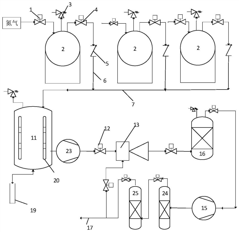
[0028] Embodiment 1: as figure 1 Shown, a kind of coking tail gas treatment method comprises the following steps:

[0029] (1) Seal the storage tank 2 storing the coking tail gas or fill it with nitrogen;

[0030] (2) discharge the coking tail gas of the storage tank 2 into the buffer tank 11 for separating the gas and liquid of the coking tail gas, and cool the preliminary dehydration, naphthalene removal and detarring in the buffer tank 11;

[0031] (3) Adopt tail gas fan 23 to suck the coking tail gas from the buffer tank 11 into the Venturi mixer 13 for removing impurities from the coking tail gas, and feed the hydrogenation gas source into the Venturi mixer 13, and the hydrogenation gas source is connected with the venturi mixer 13 The coking tail gas is fully mixed in the Venturi mixer 13, and the hydrogen content of the hydrogenation gas source is 30% to 60%;

[0032] (4) The gas mixed in the Venturi mixer 13 is discharged into the deoxygenation tank 16 for catalytic ...

Embodiment 2

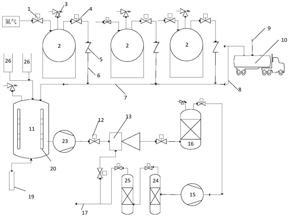
[0037] Embodiment 2: as figure 2 As shown, it is the same as in Example 1, except that the described coking tail gas treatment method also includes the step of collecting and discharging the coking tail gas of the tar ammonia water separation tank 26 that is not easy to seal and discharging it into the buffer tank 11; The tar ammonia water separation tank 26 carries out micro-positive pressure nitrogen filling process, and the nitrogen filling pressure is higher than atmospheric pressure 0-400Pa.

[0038]At the same time, it also includes the step of mixing the vehicle loading exhaust gas with the coking exhaust gas of the storage tank 2 and collecting them together into the buffer tank 11 to ensure the air pressure balance in the buffer tank 11 . That is, while collecting the coking tail gas from the storage tank 2 into the buffer tank 11, the vehicle loading tail gas is collected into the buffer tank 11 and mixed with the coking tail gas from the storage tank 2, and the loa...

Embodiment 3

[0039] Example 3, such as figure 2 As shown, the present invention also provides a device using the coking tail gas treatment method described in Embodiment 1 and 2, a coking tail gas treatment device, including at least one storage tank 2 and a buffer tank 11 that is sequentially communicated with the storage tank 2 , Venturi mixer 13, deoxygenation tank 16, the nitrogen pipeline is communicated with the top of the storage tank 2, a nitrogen charging valve 1 is provided on the nitrogen pipeline, and a quick discharge valve 3 is provided at the top of the storage tank 2; The coking tail gas in the tank 2 flows into the tail gas collection main pipe 7 through the tail gas collection branch pipe 6, and the flame arrester single exhalation valve 4 and the one-way valve 5 are arranged in sequence on the exhaust gas collection branch pipe 6, and the flame arrester single exhalation valve 4 is also installed in the storage tank top of 2;

[0040] Exhaust gas collection main pipe 7...


PUM


Abstract

The invention discloses a coking tail gas treating method and device. The method includes the following steps that storage tanks storing coking tail gas are closed or sealed through nitrogen filling;the coking tail gas of the storage tanks is charged into a buffering tank for carrying out gas-liquid separation on the coking tail gas, and is cooled and subjected to primary dewatering, naphthaleneremoving and tar removing in the buffering tank; the coking tail gas is sucked into a venture mixer for removing impurities of the coking tail gas from the buffering tank, and a hydrogenation source is introduced into the venture mixer; gas after being mixed in the venture mixer is discharged into a deoxidizing tank and subjected to catalytic hydrogenation deoxidizing; qualified coking tail gas after detection is discharged into a main gas pipe of a coking-plant gas purification system, or is discharged into a later tail gas treatment system. According to the coking tail gas treating method, the collected high-oxygen-content coking tail gas is subjected to hydrogenation deoxidizing, the oxygen content in the coking tail gas is reduced accordingly, the oxygen content in the coking tail gascan be reduced to 0.5% or below, and the coking tail gas can be directly fed into the coking-plant gas purification system and is further purified.

Description

technical field [0001] The invention belongs to the technical field of coking equipment tail gas treatment and relates to a coking tail gas treatment method and device. Background technique [0002] Coking generally refers to the process of carbonization and zooming of organic substances. In the coking plant, coking coal goes through the coking process to produce chemical products such as coke, coal tar, coke oven gas and crude benzene. The coking chemical industry only includes the coal gas purification process including condensation blast section, ammonium sulfate section, desulfurization section, debenzene section, tank farm, etc. In addition, the coking chemical industry includes tar processing, crude benzene refining, crude phenol distillation, industrial naphthalene production, asphalt Therefore, the composition of coking tail gas is very complex, except for most of it is water vapor, it also includes various macromolecular polycyclic hydrocarbons or polycyclic hydroc...

Claims


Application Information

Patent Timeline
Patent Type & Authority Patents(China)
IPC IPC(8): B01D53/86C10L3/00B01D53/90
CPCB01D53/8678B01D53/90B01D2251/202C10L3/00C10L2290/12
Inventor 梁鹏刘冰展宗城柴灵芝郭聪秦玲
Owner QINGDAO HSJ ENVIRONMENTAL PROTECTION TECH CO LTD
Why Eureka
Try Eureka