Three-stage whirling device

A swirl device and backflow device technology, which is applied in the field of gas turbine swirl device design, can solve problems such as deterioration of the combustion performance of the combustion chamber and affect the stability of the combustion chamber, and achieve the effects of improving the temperature rise capability, ensuring combustion, and reducing emissions

Inactive Publication Date: 2019-04-12
AECC SHENYANG ENGINE RES INST
View PDF7 Cites 4 Cited by
  • Summary
  • Abstract
  • Description
  • Claims
  • Application Information

AI Technical Summary

Problems solved by technology

The above-mentioned technology can meet the demand for high temperature rise of the combustion chamber to a certain extent, but it will deteriorate the combustion performance of the combustion chamber, especially affecting the stability of the combustion chamber in the idle state

Method used


Image

  • Three-stage whirling device
  • Three-stage whirling device
  • Three-stage whirling device

Examples


Embodiment Construction

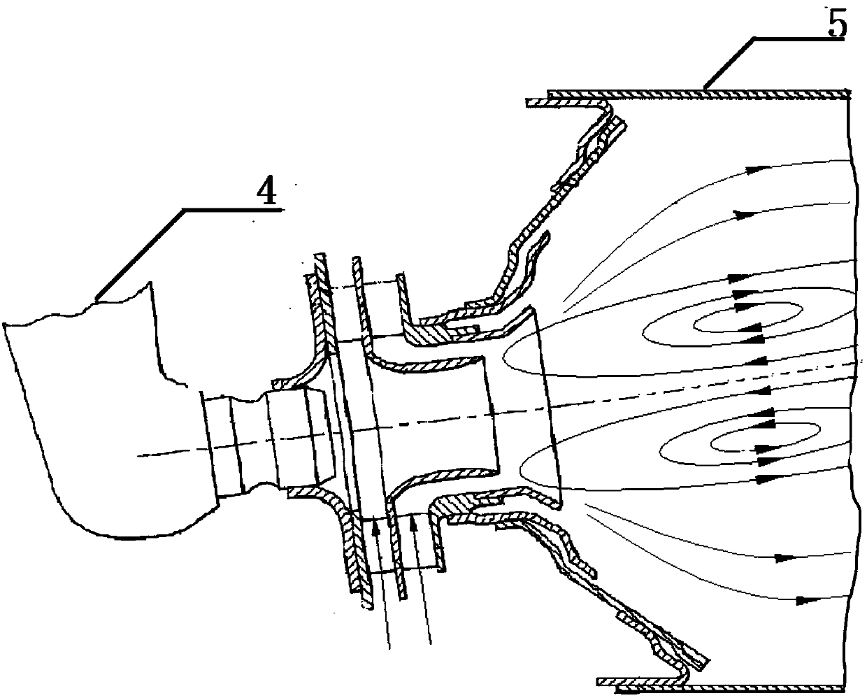
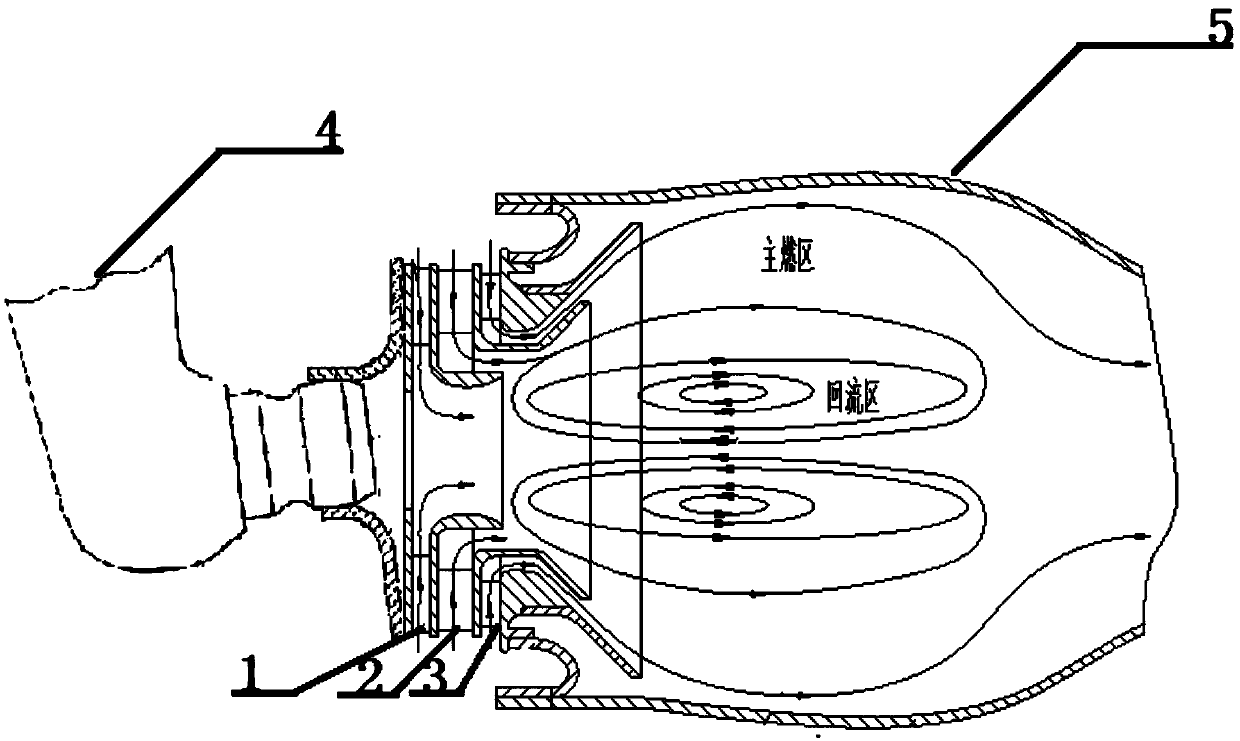
[0029] The application will be further described in detail below in conjunction with the accompanying drawings and embodiments. It should be understood that the specific embodiments described here are only used to explain the related application, not to limit the application. In addition, it should be noted that, for ease of description, only parts relevant to the present application are shown in the drawings.

[0030] It should be noted that, in the case of no conflict, the embodiments in the present application and the features in the embodiments can be combined with each other. The present application will be described in detail below with reference to the accompanying drawings and embodiments.

[0031] It should be noted that in the description of this application, the terms "center", "upper", "lower", "left", "right", "vertical", "horizontal", "inner", "outer", etc. The terms of the indicated direction or positional relationship are based on the direction or positional ...


PUM


Abstract

The invention belongs to the technical field of combustion gas turbine whirling device design, and particularly relates to a three-stage whirling device. The three-stage whirling device comprises a first-stage whirling device, a second-stage whirling device and a third-stage whirling device; the second-stage whirling device sleeves the periphery of the first-stage whirling device, and the first-stage whirling device is connected with a fuel oil nozzle; the third-stage whirling device sleeves the periphery of the second-stage whirling device and is connected with a flame tube, wherein the first-stage whirling device and the second-stage whirling device are used for inletting air into the flame tube, and the air is called backflow air; the backflow air is used for atomizing fuel oil ejectedinto the flame tube through the fuel oil nozzle and generating backflow areas in the flame tube; the third-stage whirling device can inlet air into the flame tube, and the air is called mixing air; and the mixing air flows along the inner wall of the flame tube and enters in a main combustion area of the flame tube from the periphery and the rear part of the main combustion area.

Description

technical field [0001] The application belongs to the technical field of gas turbine swirl device design, and in particular relates to a three-stage swirl device. Background technique [0002] With the development and progress of technology, the demand for large propulsion / power gas turbines for aircraft and ships is becoming more and more urgent. To obtain large thrust / power of gas turbines, a high-temperature rise of the combustion chamber is required. It reaches 1100-1300K, and its temperature rise capability is greatly improved compared with the existing conventional temperature rise combustion chamber. [0003] Existing gas turbine combustors mostly adopt double-stage swirl combustion technology, which sets the double-swirl device at the head of the combustion chamber flame tube 5, such as figure 1 As shown, the double swirl device is composed of a primary swirl device and a secondary swirl device; wherein, the primary swirl device is connected to the fuel nozzle 4; th...

Claims


Application Information

Patent Timeline
Patent Type & Authority Applications(China)
IPC IPC(8): F23R3/38F23R3/28F23R3/18
CPCF23R3/18F23R3/286F23R3/38
Inventor 赵传亮闫东博白瑞强齐健
Owner AECC SHENYANG ENGINE RES INST
Why Eureka
Try Eureka