Range hood

A range hood and flue gas technology, applied in the field of "L" type range hood, can solve the problems of limited suction and flue gas escape, and achieve the effect of improving purification efficiency

Pending Publication Date: 2019-04-12
GREE ELECTRIC APPLIANCES INC
View PDF0 Cites 1 Cited by
  • Summary
  • Abstract
  • Description
  • Claims
  • Application Information

AI Technical Summary

Problems solved by technology

[0004] Therefore, the technical problem to be solved by the present invention is to overcome the defects that the L-shaped range hood in the prior art has limited self-suction and is easy to cause smoke to escape.

Method used


Image

  • Range hood
  • Range hood
  • Range hood

Examples


Embodiment 1

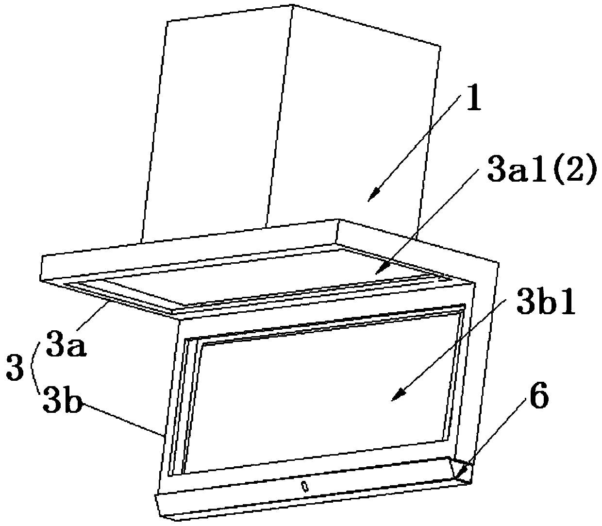
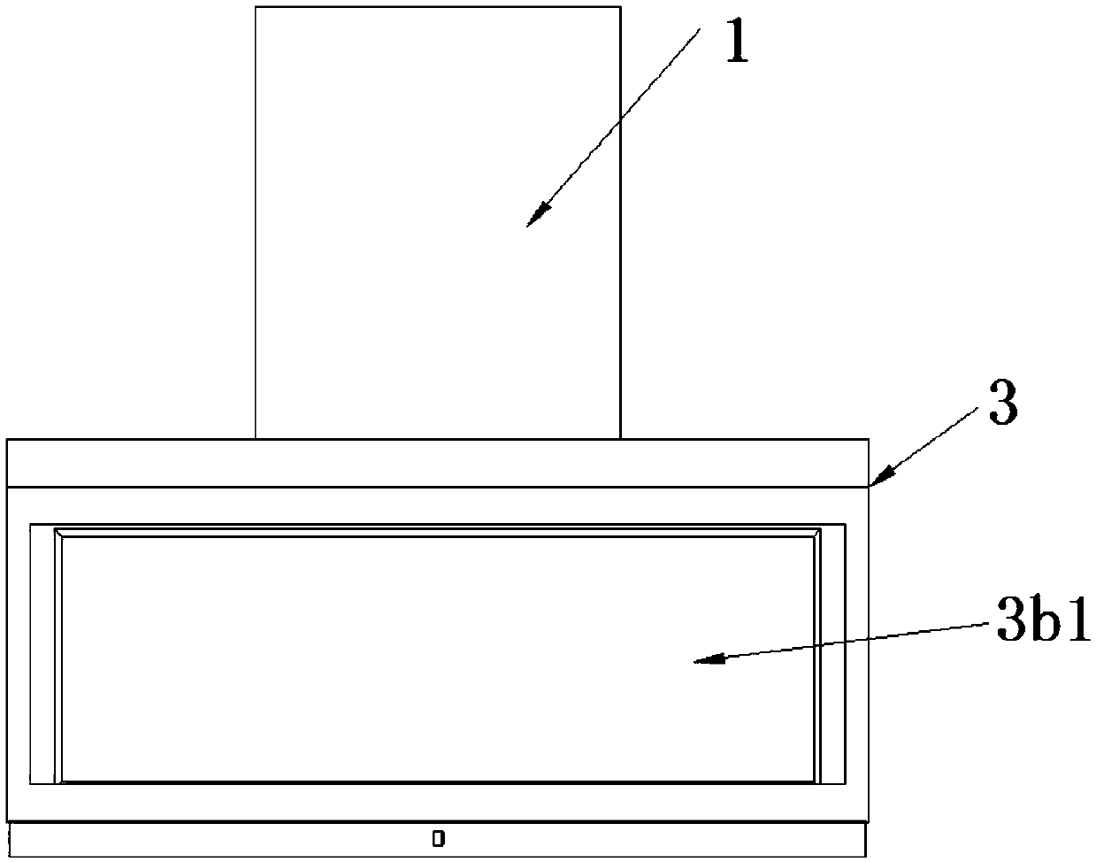
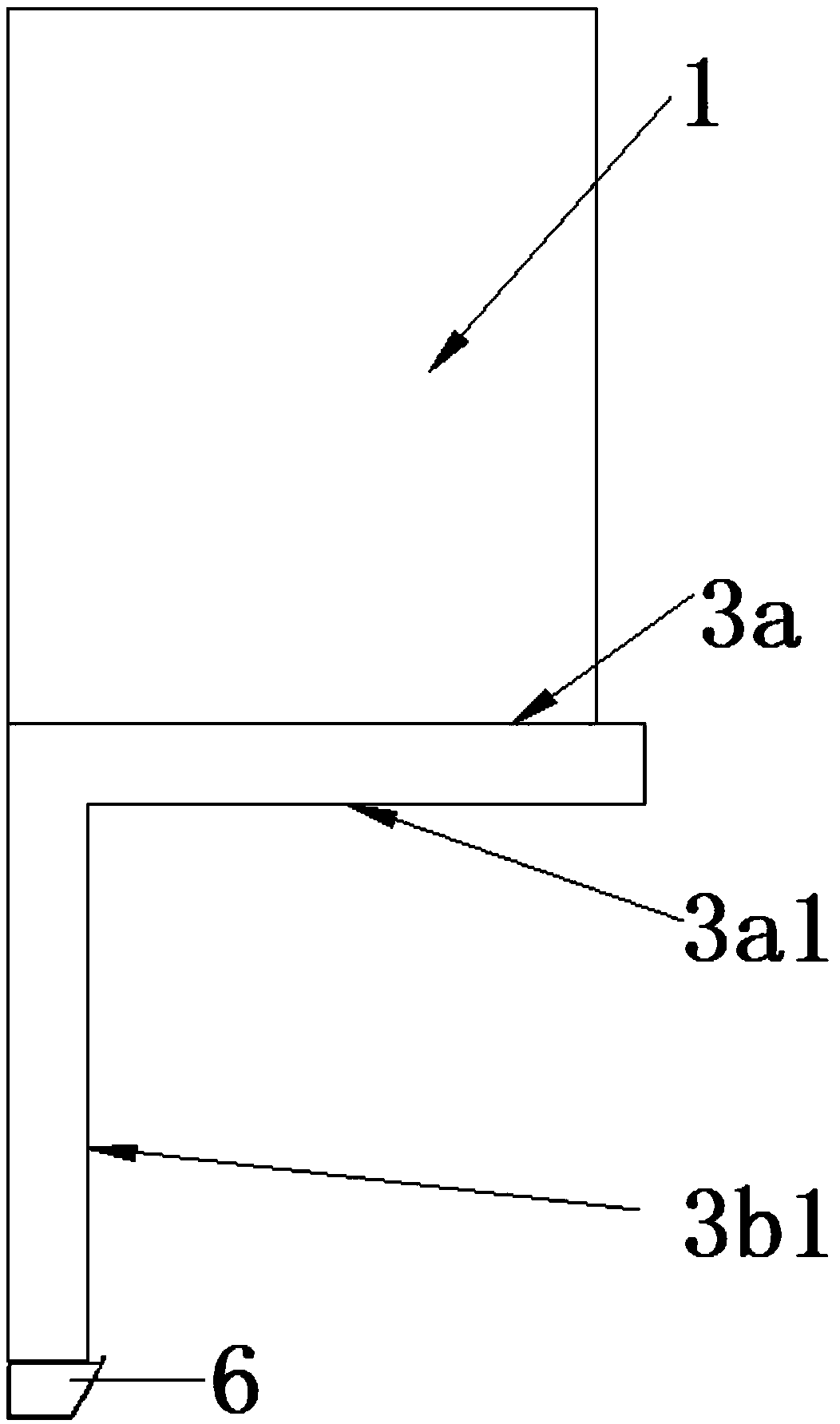
[0037] This embodiment provides a range hood, such as figure 1 , figure 2 with image 3 As shown, it includes: a chassis 1, which is provided with a housing cavity inside, and the housing cavity is provided with an air inlet 2 and an air outlet. Specifically, the air inlet 2 and the air outlet are not shown in the figure; as Figure 4 with Figure 7 As shown, the smoke collecting hood 3 includes a horizontal air-introduction part 3a and a vertical air-induction part 3b arranged at a certain angle to each other, the horizontal air-induction part 3a is provided with a top smoke inlet 3a1, and the vertical air-induction part 3b A side smoke inlet 3b1 is provided, and the smoke flowing out from the horizontal air induction part 3a and the vertical air induction enters the air inlet 2; Figure 4 The blower system 4 shown in the figure is arranged inside the accommodating cavity, including: a wind wheel 4a; a first smoke inlet 4b and a second smoke inlet 4c, which are arranged a...

Embodiment 2

[0049] This embodiment is made on the basis of Embodiment 1. This embodiment specifically provides another setting method of the partition 5. The range hood also includes at least one partition 5, and the partition 5 is installed on the On the wind wheel 4a, the partition plate 5 is arranged between the first smoke inlet 4b and the second smoke inlet 4c, and the above solution is not shown in the accompanying drawings. At the same time, there is a gap between the partition plate 5 and the wind wheel 4a in this embodiment, and the partition plate 5 is arranged on the inner wall of the cabinet 1. By setting the gap, it can be ensured that there will be no contact with the partition plate during the rotation of the wind wheel 4a. Interference between plates 5 occurs.

[0050] Specifically, the partition plate 5 can be provided in multiple pieces, so as to divide the area where the wind wheel 4a is located into a plurality of different areas.


PUM


Abstract

The invention provides a range hood. A smoke collecting cover comprises a horizontal air inducing part and a vertical air inducing part, wherein an included angle is formed between the horizontal airinducing part and the vertical air inducing part, the horizontal air inducing part is provided with a top smoke inlet, the vertical air inducing part is provided with a side smoke inlet, and smoke flowing out from the horizontal air inducing part and the vertical air inducing part enters an air inlet. The smoke collecting cover comprises the horizontal air inducing part and the vertical air inducing part, and the smoke can flow in the horizontal air inducing part and the vertical air inducing part at the same time. According to the range hood, one wind wheel is provided with two smoke inlets,the smoke flowing out from the horizontal air inducing part flows into the first smoke inlet, and the smoke flowing out from the vertical air inducing part flows into the second smoke inlet. The smokeis divided into two portions through the horizontal air inducing part and the vertical air inducing part, the two portions of smoke enter the two independent smoke inlets of the wind wheel correspondingly and then are exhausted, the smoke processing amount is doubled within the same amount of time, and meanwhile, the situation that smoke overflows due to the fact that the smoke processing amountis insufficient can be effectively avoided.

Description

technical field [0001] The invention relates to the technical field of range hoods, in particular to an "L" type range hood. Background technique [0002] Nowadays, as one of the indispensable important household appliances in the kitchen, the range hood effectively solves the problem of air quality in the kitchen and improves people's quality of life. The common range hoods on the market are mainly hung directly above the stove, which needs to occupy the space above the kitchen, resulting in an unopened kitchen space. In addition, it is easy to hit the user's head during use, resulting in a poor experience. [0003] In order to solve the above technical problems, an L-shaped range hood is provided in the prior art, which has an upper air inlet and a side air inlet. The upper air inlet and the lower air inlet correspond to a chamber respectively. The oil fume is sucked in from the upper suction port and the side suction port at the same time, then mixed in the chamber where...

Claims


Application Information

Patent Timeline
Patent Type & Authority Applications(China)
IPC IPC(8): F24C15/20
CPCF24C15/20
Inventor 董明珠梁建新许宁汪春节丁泺火孟得浩
Owner GREE ELECTRIC APPLIANCES INC
Why Eureka
Try Eureka