Multifunctional hydraulic comprehensive test bench

A comprehensive testing and multi-functional technology, applied in the direction of mechanical valve testing, testing of mechanical components, using stable tension/pressure testing material strength, etc., can solve the problems of reducing test accuracy, increasing risk factor, unfavorable test work, etc. , to achieve the effect of reducing errors, reducing risk factors, and enhancing practical performance

Active Publication Date: 2019-04-12
湖北泰和电气有限公司
View PDF6 Cites 16 Cited by
  • Summary
  • Abstract
  • Description
  • Claims
  • Application Information

AI Technical Summary

Problems solved by technology

[0003] At present, when the existing hydraulic comprehensive test bench is in the test process, the test piece is only placed directly on the placement plate or placed in the placement groove for testing, which will lead to poor stability and greatly increase the test capacity. The error reduces the accuracy of the test, and when the current test bench places the test piece, the place plate is fixed and located under the hydraulic push rod, which will increase the risk factor and is not conducive to the test work. Therefore, it is necessary to A Multifunctional Hydraulic Comprehensive Test Bench

Method used


Image

  • Multifunctional hydraulic comprehensive test bench
  • Multifunctional hydraulic comprehensive test bench
  • Multifunctional hydraulic comprehensive test bench

Examples


Embodiment Construction

[0022] The following will clearly and completely describe the technical solutions in the embodiments of the present invention with reference to the accompanying drawings in the embodiments of the present invention. Obviously, the described embodiments are only some, not all, embodiments of the present invention.

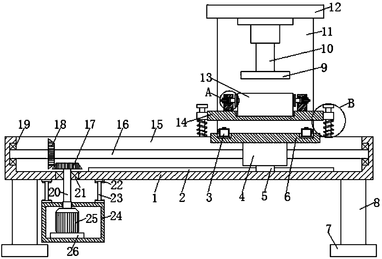
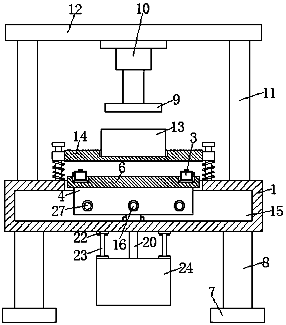
[0023] refer to Figure 1-5 , a multifunctional hydraulic comprehensive test bench, comprising a platform 1, support legs 8 are fixedly installed at the four corners of the bottom surface of the platform 1, and anti-slip mats 7 are fixedly installed at the lower ends of the support legs 8, through which the anti-slip mat 7 can effectively The anti-slip function of the test bench improves the stability and firmness of the overall structure of the test bench.

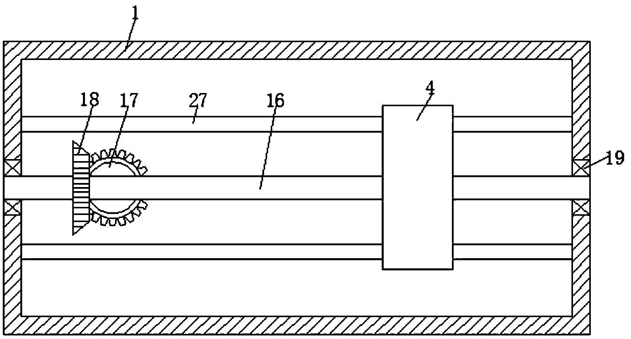
[0024] The upper surface of the platen 1 is provided with a groove 15, and the middle part of both sides of the inner wall of the groove 15 is provided with a first bearing 19, and an adjusting rod 16 is arrange...


PUM


Abstract

The invention relates to the technical field of hydraulic test equipment, in particular to a multifunctional hydraulic comprehensive test bench, comprising a platen. A groove is formed on the upper surface of the platen. A first bearing is though provided on the middle of each of the two sides of the inner wall of the groove. An adjusting rod is rotationally provided between the two first bearings. A pressure sensor is fixedly mounted at each of the four corners of the upper surface of the movable plate. A supporting plate is fixedly mounted on each of the two ends of one side of the upper surface of the platen. A top cover is fixedly mounted on the upper end of each of the supporting plates. A hydraulic push rod is fixedly mounted at the middle of the lower surface of the top cover. A pressing plate is fixedly mounted at the lower end of the hydraulic push rod. Four positioning mechanisms are fixedly mounted on one side of the upper surface of the platen. A placing plate is fixedly mounted among the four positioning mechanisms. A mounting groove is formed on the upper portion of one side of the fixed block. A second sliding groove is fixedly mounted on each of the two sides of theinner wall of the mounting groove. According to the multifunctional hydraulic comprehensive test bench, a test piece can be fixed and adjusted, the operation is simple, the use is convenient and thepracticability is high.

Description

technical field [0001] The invention relates to the technical field of hydraulic testing equipment, in particular to a multifunctional hydraulic comprehensive testing platform. Background technique [0002] The application range of the hydraulic test bench is 0-300Mpa static pressure and hydraulic test, which can meet the explosive test of pipe fittings, valves, gas cylinders and other products. [0003] At present, when the existing hydraulic comprehensive test bench is in the test process, the test piece is only placed directly on the placement plate or placed in the placement groove for testing, which will lead to poor stability and greatly increase the test capacity. The error reduces the accuracy of the test, and when the current test bench places the test piece, the place plate is fixed and located under the hydraulic push rod, which will increase the risk factor and is not conducive to the test work. Therefore, it is necessary to The utility model relates to a multif...

Claims


Application Information

Patent Timeline
Patent Type & Authority Applications(China)
IPC IPC(8): G01M13/00G01M13/003G01N3/12G01N3/02
CPCG01M13/00G01N3/02G01N3/12G01N2203/0019G01N2203/0048G01N2203/0274
Inventor 骆仁星郑刚王正虎毕方坤
Owner 湖北泰和电气有限公司
Why Eureka
Try Eureka