Three-dimensional measuring method and measuring device for converter furnace chamber based on three-dimensional laser radar auxiliary positioning

A three-dimensional laser, auxiliary positioning technology, applied in the field of three-dimensional measurement, can solve the problems of inability to determine the relative position of three-dimensional coordinates, destruction of markers, clumsy self-positioning technology, etc.

Active Publication Date: 2019-04-12
ZHEJIANG UNIV
View PDF7 Cites 7 Cited by
  • Summary
  • Abstract
  • Description
  • Claims
  • Application Information

AI Technical Summary

Problems solved by technology

The disadvantage of this method is that it is difficult for the scanner to identify the markers, and the temperature of the converter mouth is as high as 2000 degrees Celsius, which will cause damage to the markers
The disadvantage is that this point method can only determine the scanning position of the 3D laser scanner, the relative position of the 2D coordinates, and cannot determine the relative position of the 3D coordinates. If the 3D laser scanner is not placed accurately and horizontally, the point accuracy will be significantly reduced
[0006] To sum up, the currently used scanner self-positioning technology is clumsy, and it is difficult for the scanner to identify markers. Moreover, the temperature of the converter mouth is as high as 2000 degrees Celsius, which will damage the markers; positioning takes time and cannot meet the requirements of converter steelmaking. Beat; low positioning accuracy

Method used


Image

  • Three-dimensional measuring method and measuring device for converter furnace chamber based on three-dimensional laser radar auxiliary positioning
  • Three-dimensional measuring method and measuring device for converter furnace chamber based on three-dimensional laser radar auxiliary positioning
  • Three-dimensional measuring method and measuring device for converter furnace chamber based on three-dimensional laser radar auxiliary positioning

Examples


Embodiment Construction

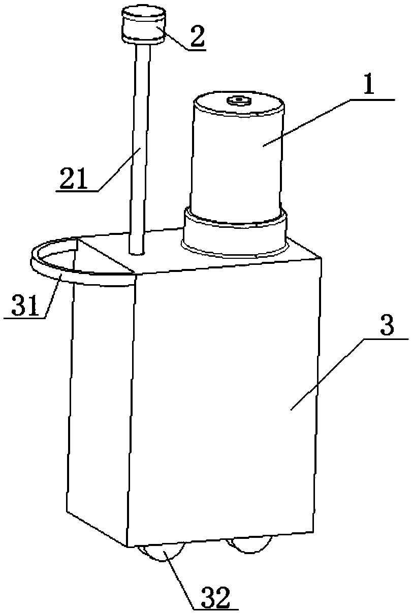
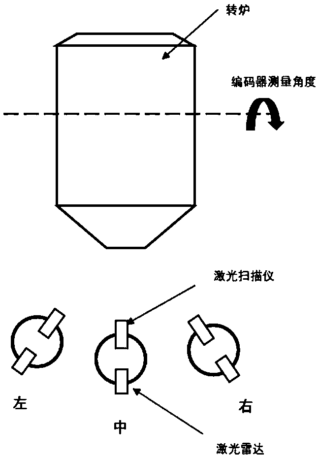
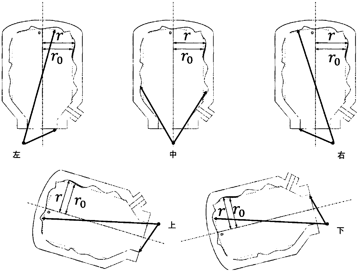
[0095] In the present invention, the three-dimensional laser scanner is fixedly connected with the three-dimensional laser radar, while the three-dimensional laser scanner is moved, the steel factory workshop environment is scanned by the three-dimensional laser radar, and the relative pose of the three-dimensional laser scanner in the three-dimensional space is obtained, and the three-dimensional The three-dimensional point cloud of the converter cavity from various angles of the laser scanner is spliced ​​to obtain a complete three-dimensional point cloud of the converter cavity, which is compared with the CAD model to obtain the thickness change of the converter cavity, real-time monitoring of the wear of the converter cavity, and indicating the need for repair of the converter place to judge whether the converter should be scrapped.

[0096] The present invention will be further described below in conjunction with the accompanying drawings and specific embodiments.

[0097...


PUM


Abstract

The invention discloses a three-dimensional measuring method and measuring device for a converter furnace chamber based on three-dimensional laser radar auxiliary positioning. The measuring method andthe measuring device obtain three-dimensional point cloud of the converter furnace chamber at various angles of view by moving a three-dimensional laser scanner, at that same time, three-dimensionallaser radar scan the workshop environment of a steel mill, the relative position of the three-dimensional laser scanner in the three-dimensional space is obtained by three-dimensional laser radar, thethree-dimensional point cloud of the converter furnace chamber at various angles of view of the three-dimensional laser scanner is registered, the complete actual three-dimensional point cloud of theconverter furnace chamber is obtained by splicing, the thickness change of the converter furnace chamber is obtained by comparing with an original furnace chamber model, the wear condition of the converter furnace chamber is monitored in real time, the place of the converter needing to be repaired is indicated, whether the converter should be discarded is judged, quick and accurate positioning ofthe scanner is realized, and the measuring accuracy is improved.

Description

technical field [0001] The invention relates to the field of three-dimensional measurement, more specifically, it relates to a method and device for three-dimensional measurement of a converter cavity based on three-dimensional laser radar-assisted positioning. Background technique [0002] In many metallurgical enterprises in my country, the converter is widely used as an important steelmaking tool. The role of the converter is to melt the metal ore poured from the hopper and turn the metal ore into molten metal. However, during the working process of the converter, the molten metal in the converter cavity continuously corrodes the converter cavity, resulting in the thickness of the converter cavity becoming thinner and thinner. When the thickness of the converter cavity is lower than a certain value, the converter will appear "red", or the molten steel will pass through the furnace, which will not only damage the equipment, but also seriously threaten the personal safety ...

Claims


Application Information

Patent Timeline
IPC IPC(8): G01S17/42G01B11/06
CPCG01B11/06G01S17/42
Inventor 杨将新陶阳曹衍龙任立飞董献瑞
Owner ZHEJIANG UNIV
Why Eureka
Try Eureka