Orthopedic clinical fracture continuation device

A technology for bone replacement and orthopedics, which is applied in the field of bone replacement devices for clinical fractures in orthopedics. It can solve the problems of aggravating the disease, suffering patients, increasing the labor intensity of medical staff, etc., and achieve the effect of reducing labor intensity and avoiding pain.

Active Publication Date: 2019-04-16
刘伟
View PDF7 Cites 2 Cited by
  • Summary
  • Abstract
  • Description
  • Claims
  • Application Information

AI Technical Summary

Problems solved by technology

Patients often suffer from fractures at one site, and a few suffer from multiple fractures. After timely and appropriate treatment, most patients can recover their original functions, and a few patients may have sequelae of varying degrees. After fractures, those who are closer to the hospital can be sent directly to Hospital or call an ambulance. Patients who are far away from the hospital must undergo simple treatment to prevent their condition from aggravating on the way to the hospital, or even cause irreversible consequences. Severe fractures need to be combined with broken bones. During this process, usually Bone plate is used to connect two broken bones, and the ends of both sides need to be drilled during bone set, and then the bone set screw is fixed. However, when the existing bone set is fixed, the patient needs to lift the leg and place it Put it on the frame or lift it with the help of medical staff, which not only increases the labor intensity of the medical staff, but also brings pain to the patient. On the other hand, the patient cannot fix the root after placing the leg on the bone extension device, resulting in The position is easy to shift when fixing the hole, and the position of the fixing device on the top cannot be adjusted, which cannot meet the needs of patients with fractures at different positions, and thus cannot meet the higher needs of users

Method used


Image

  • Orthopedic clinical fracture continuation device
  • Orthopedic clinical fracture continuation device
  • Orthopedic clinical fracture continuation device

Examples


Embodiment

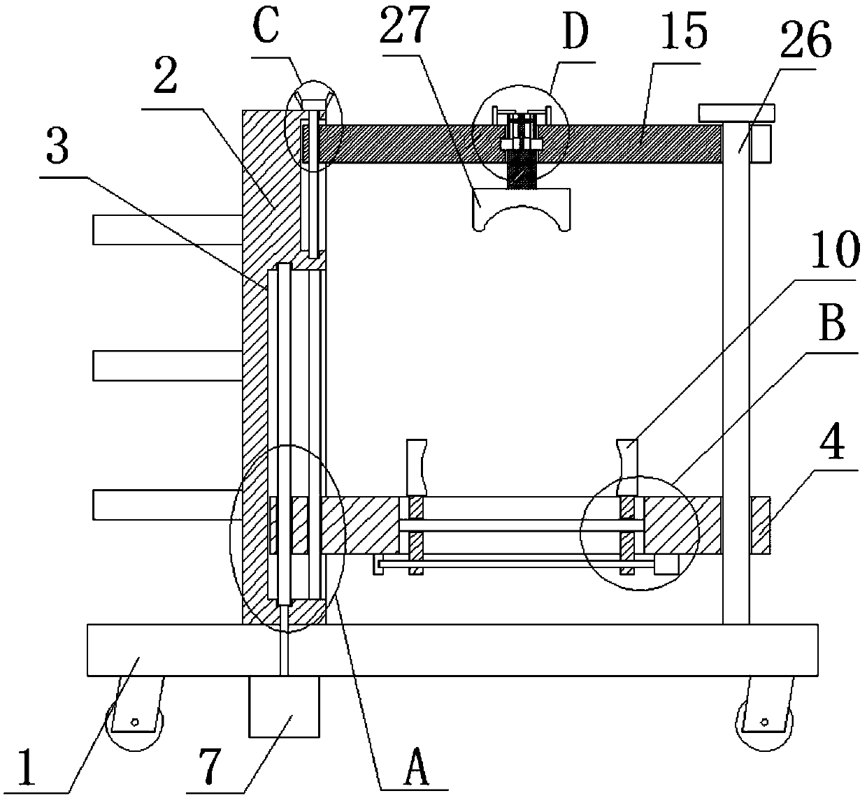
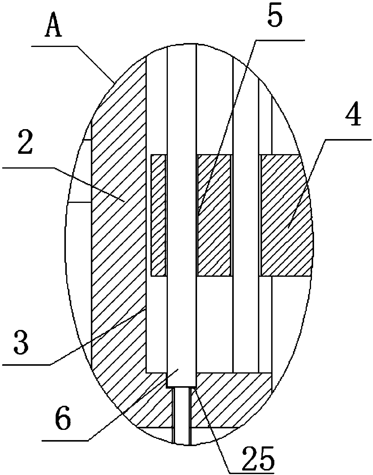
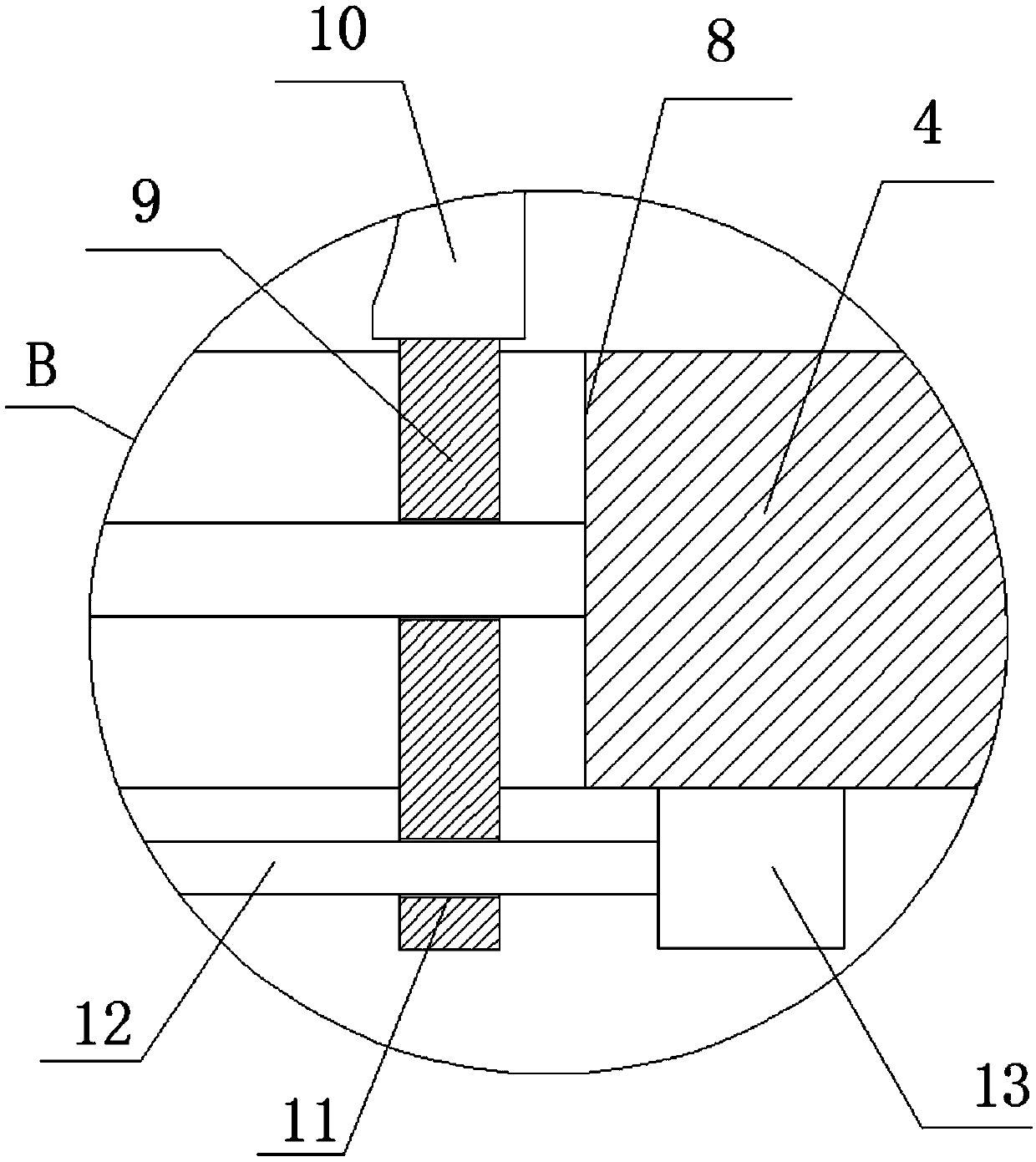
[0023] refer to Figure 1-5, the present embodiment proposes a kind of orthopedic clinical fracture bone device, including a base 1, the top of the base 1 is welded with a vertical plate 2, a groove 3 is opened on one side of the vertical plate 2, and an auxiliary device is slidably installed in the groove 3. Plate 4, the top of the auxiliary plate 4 is welded with a first threaded hole 5, the internal thread of the first threaded hole 5 is installed with a ball screw 6, the bottom of the base 1 is welded with a first forward and reverse motor 7, and the first forward and reverse motor The output shaft of 7 is welded to the bottom of the ball screw 6, and the top of the auxiliary plate 4 is provided with a sliding hole 8, and two moving rods 9 are slidably installed in the sliding hole 8, and the tops of the two moving rods 9 are welded with clamping Seat 10, the two clamping seats 10 are compatible, one side of the two moving rods 9 is provided with a second threaded hole 11,...


PUM


Abstract

The invention discloses an orthopedic clinical fracture continuation device comprising a base. A vertical plate is welded at the top of the base, a groove is formed in one side of the vertical plate,an auxiliary plate is mounted in the groove in the sliding mode, a first threaded hole is welded at the top of the auxiliary plate, a ball screw is mounted in the first threaded hole through threads,a first forward and reverse motor is welded at the bottom of the base, and an output shaft of the first forward and reverse motor is welded to the bottom end of the ball screw. A sliding hole is formed in the top of the auxiliary plate, and two moving rods are installed in the sliding hole in the sliding mode. The device is economical and practical, and can automatically drive the legs of a patient to be lifted for treatment, which not only reduces the labor intensity of medical staff, but also avoids pains to the patient. The device can also be used for fixing according to the legs of different patients, no position deviation is caused during perforation, the position of a top adjusting arm can also be adjusted according to the actual conditions of the patients, and the device can be usedby the patients with different fractures.

Description

technical field [0001] The invention relates to the clinical technical field of orthopedics, in particular to a clinical bone fracture device for orthopedics. Background technique [0002] Orthopedics is one of the most common departments in major hospitals. It mainly studies the anatomy, physiology and pathology of the musculoskeletal system, and uses drugs, surgery and physical methods to maintain and develop the normal shape and function of this system. The so-called fracture, as the name implies, refers to Complete or partial fracture of bone or bone structure is more common in children and the elderly, and sometimes occurs in young and middle-aged people. Patients often suffer from fractures at one site, and a few suffer from multiple fractures. After timely and appropriate treatment, most patients can recover their original functions, and a few patients may have sequelae of varying degrees. After fractures, those who are closer to the hospital can be sent directly to ...

Claims


Application Information

Patent Timeline
Patent Type & Authority Applications(China)
IPC IPC(8): A61G13/12A61B90/14
CPCA61G13/1245A61G2203/70A61G2210/10A61B90/14
Inventor 刘伟辛凤芹
Owner 刘伟
Why Eureka
Try Eureka