
Right and left hand interchange mechanism for rope-driven upper limb rehabilitation trainer

A rope-driven, trainer technology, applied in passive exercise equipment, physical therapy and other directions, can solve the problems of increased difficulty, complex reversing structure, and low utilization rate of the upper limb rehabilitation training mechanical arm, and achieves the effect of improving the use efficiency.

Active Publication Date: 2019-04-16
SUZHOU HAOBRO MEDICAL DEVICE
View PDF7 Cites 6 Cited by
  • Summary
  • Abstract
  • Description
  • Claims
  • Application Information

AI Technical Summary

Problems solved by technology

[0003] There are not many studies on the cable-type rehabilitation manipulator in the current frontier of science and technology. The reason may be that the design difficulty of the driving method of the cable will increase, and the utilization rate of the upper limb rehabilitation training manipulator is not high. The reversing structure of the robotic arm for left / right arm separate training is relatively complicated. Based on the current problems, we designed and developed a left / right hand interchange mechanism for the rope-driven upper limb rehabilitation trainer

Method used


Image

  • Right and left hand interchange mechanism for rope-driven upper limb rehabilitation trainer
  • Right and left hand interchange mechanism for rope-driven upper limb rehabilitation trainer
  • Right and left hand interchange mechanism for rope-driven upper limb rehabilitation trainer

Examples


Embodiment

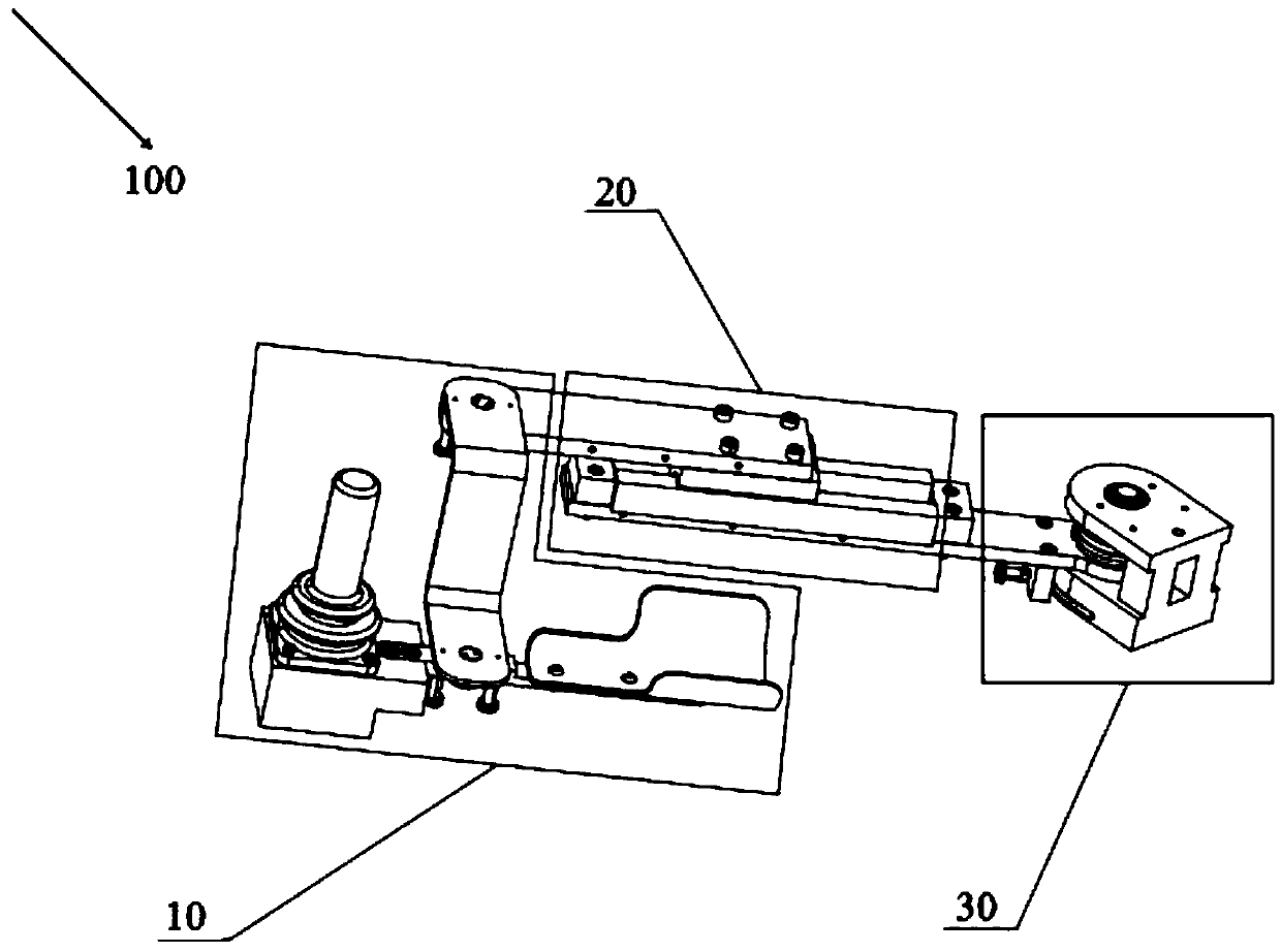
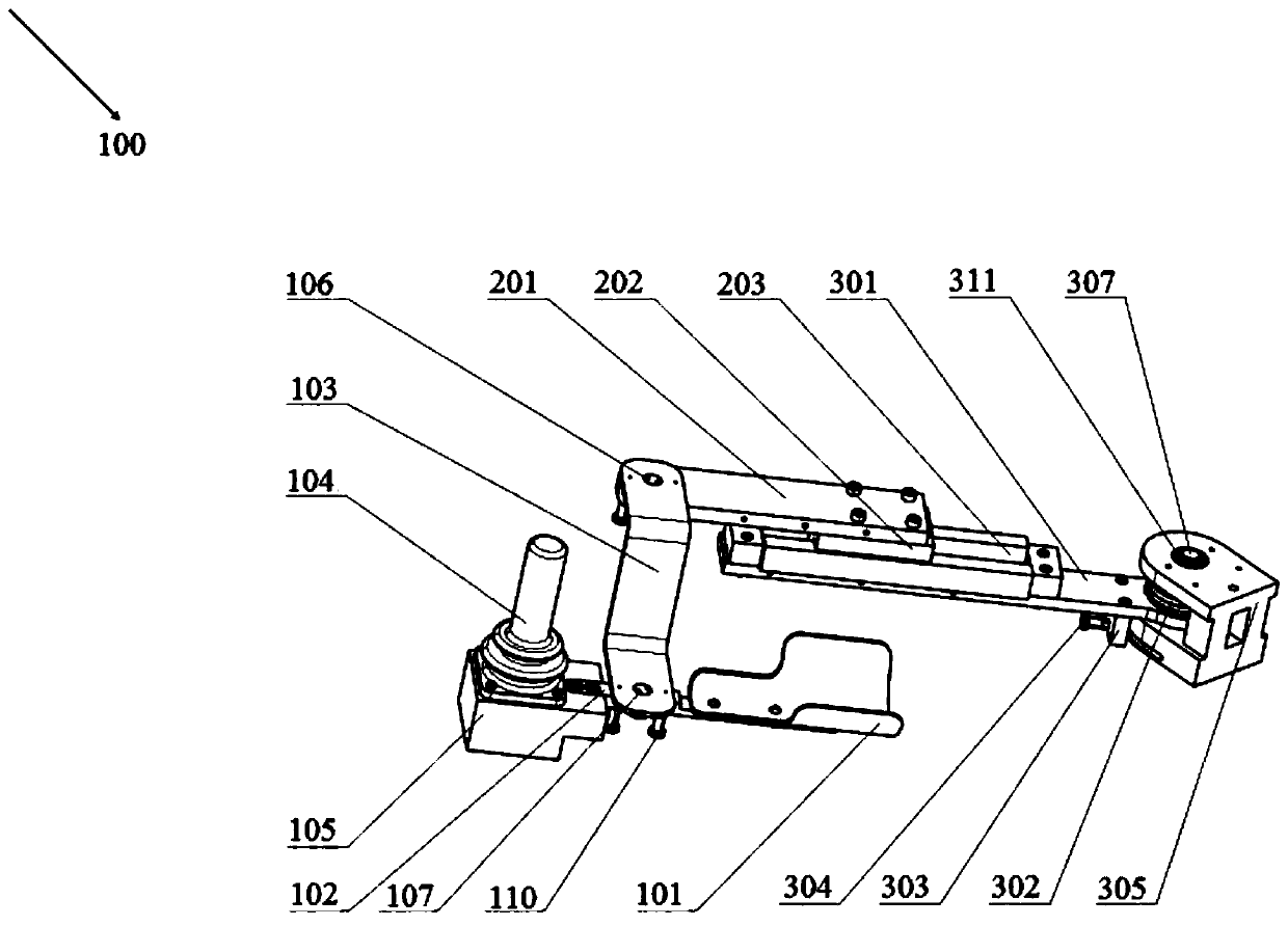
[0022] figure 1 It is a schematic diagram of the overall structure of the left and right hand exchange mechanism for the rope-driven upper limb rehabilitation training device in the embodiment of the present invention, figure 2 It is a structural schematic diagram of the adduction state of the mechanical arm of the left and right hand exchange mechanism for the rope-driven upper limb rehabilitation training device in the embodiment of the present invention

[0023] Such as figure 1 and figure 2 As shown, a left and right hand exchange mechanism 100 for a rope-driven upper limb rehabilitation training device in this embodiment includes: a wrist reversing part 10 , a forearm compensating part 20 and an elbow flexion and extension part 30 .

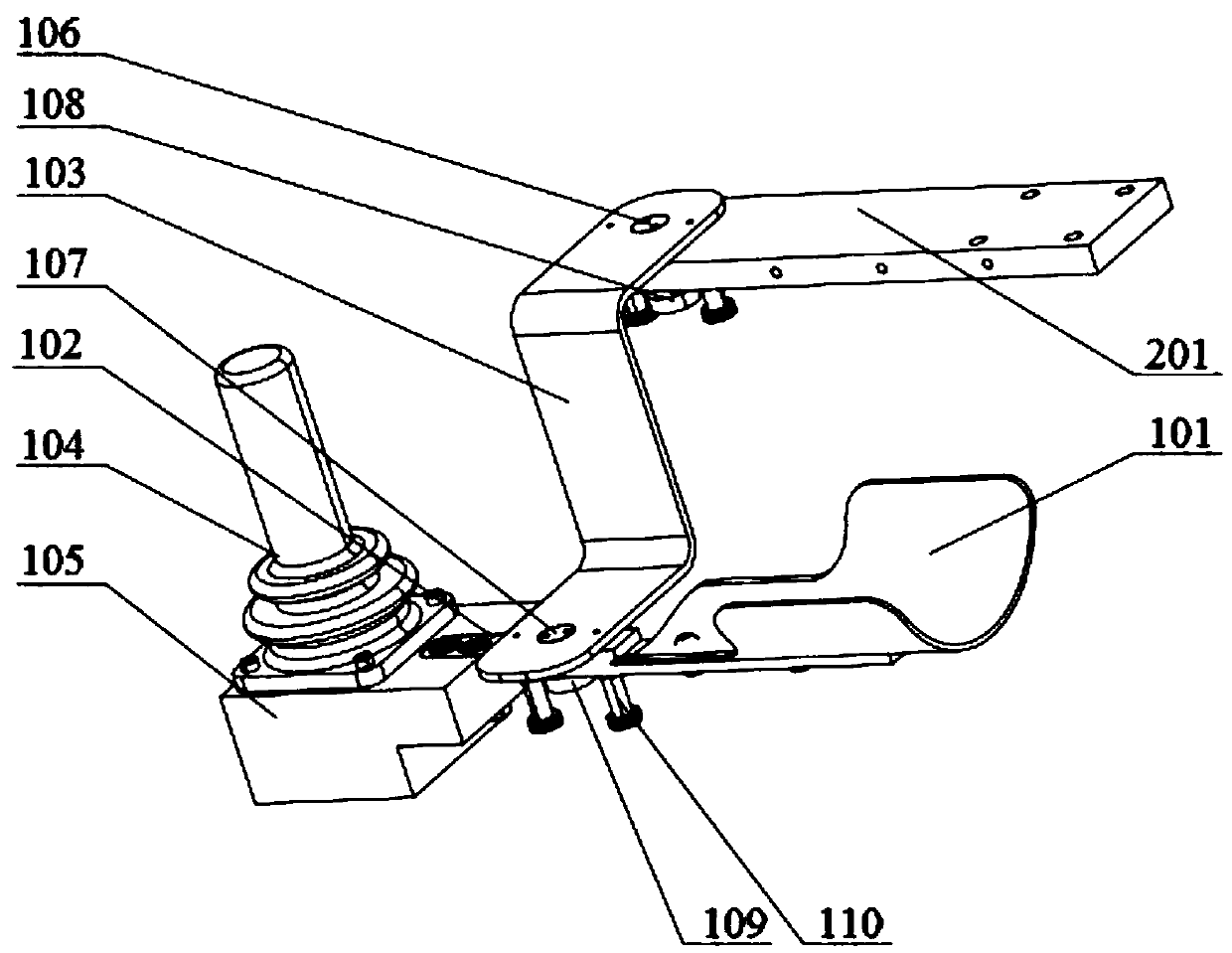
[0024] image 3 It is a structural schematic diagram of the wrist reversing part of the left and right hand exchange mechanism used for the rope-driven upper limb rehabilitation training device in the embodiment of the present invention...


PUM


Abstract

The present invention provides a right and left hand interchange mechanism for a rope-driven upper limb rehabilitation trainer. The right and left hand interchange mechanism includes a wrist reversingportion, a forearm compensating portion and an elbow flexing and extending portion, wherein the wrist reversing portion includes a supporting plate for supporting a wrist, a narrow connecting plate fixed to the bottom of the supporting plate, a Z-shaped connecting plate with one end fixed to the narrow connecting plate and adjacent to the supporting plate, and a Hall operating rod disposed on oneside of the Z-shaped connecting plate; the forearm compensating portion includes a short connecting plate connected to the other end of the Z-shaped connecting plate, a sliding block connected with the short connecting plate through a screw and a linear guideway guide groove where the sliding block is embedded and which is used for the movement of the sliding block; and the elbow flexing and extending portion includes a forearm connecting rod connected with the linear guideway guide groove, an elbow pull cable wheel connected with the forearm connecting rod through a pin, an elbow limiting fixed block fixed at the bottom of the forearm connecting rod through a pin, two reversing positioning pins disposed on the elbow limiting fixed block, a C-shaped joint connector for placing the elbow pull cable wheel and the end of the forearm connecting rod at the position of an opening, and a flexing and extending rotating shaft passing through through holes in a top plate and a base plate of theC-shaped joint connector, the elbow pull cable wheel and the end of the forearm connecting rod.

Description

technical field [0001] The invention relates to an upper limb rehabilitation mechanical mechanism driven by a rope, in particular to a left and right hand exchange mechanism used for a rope-driven upper limb rehabilitation training device. Background technique [0002] With the continuous development of the times, the health care work for the elderly and the disabled has gradually been replaced by more intelligent and convenient rehabilitation robotic arms. In order to adapt to the concept of family rehabilitation nursing, the rehabilitation robotic arm has begun to develop in a more intelligent and compact direction. , The appearance of the cable type upper limb rehabilitation manipulator broke the design idea of ​​the traditional rehabilitation manipulator. Each joint of the traditional rehabilitation robotic arm needs to be equipped with a motor, which not only increases the burden on the operation of the rehabilitation robotic arm, but also seriously affects the nursing ...

Claims


Application Information

Patent Timeline
Patent Type & Authority Applications(China)
IPC IPC(8): A61H1/02
CPCA61H1/0274A61H1/0277A61H2201/123A61H2201/1659
Inventor 孟巧玲罗胜利张伟胜黄小海杜佳昊余杰喻洪流
Owner SUZHOU HAOBRO MEDICAL DEVICE
Learn More