Auxiliary welding tool for flange of winding drum

An auxiliary welding and reeling technology, applied in auxiliary welding equipment, auxiliary devices, welding equipment, etc., can solve the problems of affecting the stability of the reel support, destroying the overall structure of the reel, and easily generating axial jumps, so as to avoid moving , Avoid secondary clamping and ensure the effect of stability

Active Publication Date: 2022-06-07
SHANDONG HUIFENG CASTING TECH
View PDF7 Cites 3 Cited by
  • Summary
  • Abstract
  • Description
  • Claims
  • Application Information

AI Technical Summary

Problems solved by technology

[0004] The purpose of the present invention is to overcome the deficiencies in the prior art and provide an auxiliary welding tool for the reel flange to solve the problem that the existing reel flange will destroy the overall structure of the reel during welding, which will easily cause deformation of the rope groove and damage the reel. Under the support of the outer support, it is easy to produce axial jump when rotating, which affects the stability of the drum support

Method used


Image

  • Auxiliary welding tool for flange of winding drum
  • Auxiliary welding tool for flange of winding drum
  • Auxiliary welding tool for flange of winding drum

Examples


Embodiment 1

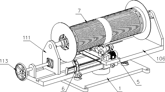
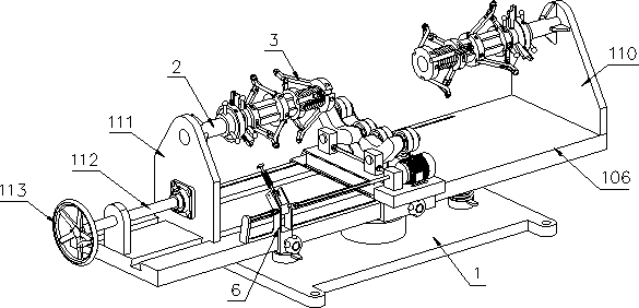
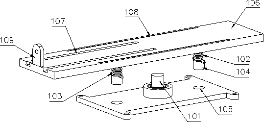
[0052] like Figure 1-3As shown, a reel sidewall auxiliary welding tool includes a bottom plate 106, a reel clamping fixture 3, and a sidewall fixture 4. The upper side of the bottom plate 106 is provided with a number of first guide grooves 107, and one end of the bottom plate 106 is provided with a The fixed seat 110, the other end of the bottom plate 106 is provided with a sliding seat 111 that is slidably mounted inside the first guide groove 107, and one end of the bottom plate 106 close to the sliding seat 111 is provided with a support plate 109, and the support plate 109 is threadedly connected with an adjusting screw 112 , one end of the adjusting screw 112 is movably connected with the sliding seat 111, and the other end of the adjusting screw 112 is provided with a hand wheel 113; the adjusting screw 112 is used to adjust the distance between the fixed seat 110 and the sliding seat 111, so as to facilitate the reels of different lengths Supporting use; one side of t...

Embodiment 2

[0059] The difference from Example 1 is that, as Figure 11 As shown, in this embodiment, the reel pressing fixture 3 includes a plurality of L-shaped fixing brackets 313 fixedly installed on the support arm 2 and a cone 309 slidably installed on the support arm 2. One end is provided with a first bushing 314, a third support rod 311 is slidably installed inside the first bushing 314, the upper end of the third support rod 311 is rotatably connected with a support wheel 312, and the cone 309 is provided with several The guide rail 310 and the lower end of the third support rod 311 are connected with a guide wheel, and the guide wheel is slidably installed inside the guide rail 310 . When the reel 7 is pressed tightly, the first screw sleeve 308 is rotated to move the cone 309 to the middle of the reel 7. When the cone 309 moves, the guide wheel at the lower end of the third support rod 311 slides on the outer wall of the cone 309 to drive the first The three support rods 311 ...

Embodiment 3

[0063] The difference from Example 1 is that, as Figure 12-14As shown, in this embodiment, the beating mechanism includes a second drive bevel gear 612 fixedly mounted on the connecting sleeve 604, and two sets of second shaft sleeves 614 are connected to the inner side of the support frame 601. A drive shaft 615 is rotatably connected to the second bushing 614. The lower end of the drive shaft 615 is provided with a second driven bevel gear 613 meshing with the second drive bevel gear 612, and the upper end of the drive shaft 615 is provided with a plurality of drive teeth 617. The upper second shaft sleeve 614 is provided with a beating shaft 616, and there are several guide grooves (not shown in the figure) on the side wall of the jumping shaft 616. A guide bar (not shown in the figure), so that the jumping shaft 616 can only slide up and down in the second sleeve 614, but cannot rotate in the second sleeve 614; the lower end of the jumping shaft 616 is provided with a plu...


PUM


Abstract

The auxiliary welding tool comprises a bottom plate, a winding drum jacking clamp and a flange clamp, a fixing base is arranged at one end of the bottom plate, and a sliding base installed in a first guide groove in a sliding mode is arranged at the other end of the bottom plate; one side of the fixed seat and one side of the sliding seat are rotationally connected with supporting arms, the winding drum jacking clamp is arranged in the winding drum, and the winding drum jacking clamp is of a retractable structure; the flange clamp comprises a chuck body, a bevel gear wheel is arranged in the chuck body, a spiral groove is formed in one side of the bevel gear wheel, a plurality of clamping jaws are spirally connected to one side of the spiral groove, steps are arranged at the tail ends of the clamping jaws, and the clamping jaws are slidably connected with the chuck body. And one side of the bevel gear wheel is meshed with a plurality of bevel pinions. According to the winding drum jacking clamp, the inner wall of the winding drum is jacked, damage to a winding drum rope groove when the winding drum is supported is avoided, meanwhile, axial jumping generated when the winding drum is rotated in the welding process is avoided, the winding drum supporting stability is guaranteed, and then the welding quality of a flange and the winding drum is guaranteed.

Description

technical field [0001] The invention belongs to the technical field of reel welding, and in particular relates to an auxiliary welding tool for the sidewall of a reel. Background technique [0002] As a key accessory of hoisting equipment, the drum is widely used in high-end engineering equipment such as crawler, rotary drilling rig, port crane, large tower crane, etc. The performance of the drum determines the height and tonnage of the hoisting equipment, and even seriously affects the The service life of the wire rope. The reel generally includes a cylinder with a spiral rope groove and ribs (flanges) welded at both ends of the cylinder. When the ribs are welded to the cylinder, it is not only necessary to ensure the parallelism of the ribs on both sides, but also the ribs. Perpendicularity to the barrel. [0003] The Chinese utility model patent with publication number CN210209265U discloses an electric hoist reel shell welding fixture, and specifically discloses: the f...

Claims


Application Information

Patent Timeline
Patent Type & Authority Applications(China)
IPC IPC(8): B23K37/047B23K37/00B23K37/08
CPCB23K37/047B23K37/00B23K37/08Y02E60/10
Inventor 刘庆坤刘宪民刘明亮周长猛巩传海焦方立贾鹏徐腾李扬王广宝
Owner SHANDONG HUIFENG CASTING TECH
Why Eureka
Try Eureka