Glue production and processing system
A processing system and glue technology, applied in the directions of dissolution, mixer, chemical instruments and methods, etc., can solve the problems of agitator damage and lack of elasticity, and achieve the effect of reducing the probability of damage
- Summary
- Abstract
- Description
- Claims
- Application Information
AI Technical Summary
Problems solved by technology
Method used
Image

Examples
specific Embodiment approach 1
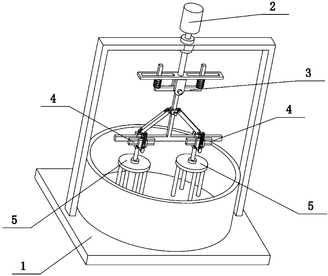
[0025] Combine below Figure 1-8 To illustrate this embodiment, the present invention relates to the field of glue production, more specifically a glue production and processing system, including a main frame body 1, a driving mechanism 2, a swing frame 3, a sliding sleeve assembly 4 and a stirring assembly 5. The present invention can The swing frame 3 can swing left and right. When the swing frame 3 swings left and right, it will be affected by the compression spring 3-3, so that the swing frame 3 can return to its original position. When mixing high-viscosity glue, the swing frame 3 can Elastic swing is performed to reduce the probability of damage to the stirring assembly 5; and the sum of the positions of the two stirring assemblies 5 can be adjusted as required.
[0026] The drive mechanism 2 is rotatably connected to the upper end of the main frame body 1, the upper end of the swing frame 3 is hingedly connected to the lower end of the drive mechanism 2, and two sliding...
specific Embodiment approach 2
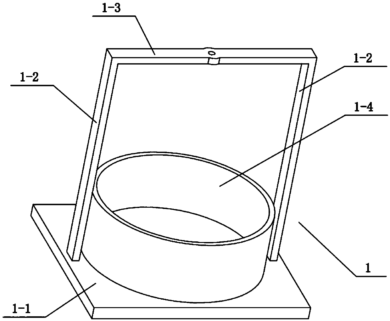
[0027] Combine below Figure 1-8 To illustrate this embodiment, the main frame body 1 includes a bottom plate 1-1, a support vertical bar 1-2, a beam bar 1-3 and a glue container 1-4, and the upper end of the bottom plate 1-1 is provided with a glue container 1-4, The left and right ends of the bottom plate 1-1 are fixedly connected with support vertical rods 1-2, and the upper ends of the two support vertical rods 1-2 are fixedly connected with cross beam rods 1-3. Glue container 1-4 is used for adding raw material and additive, from preparing glue.
specific Embodiment approach 3
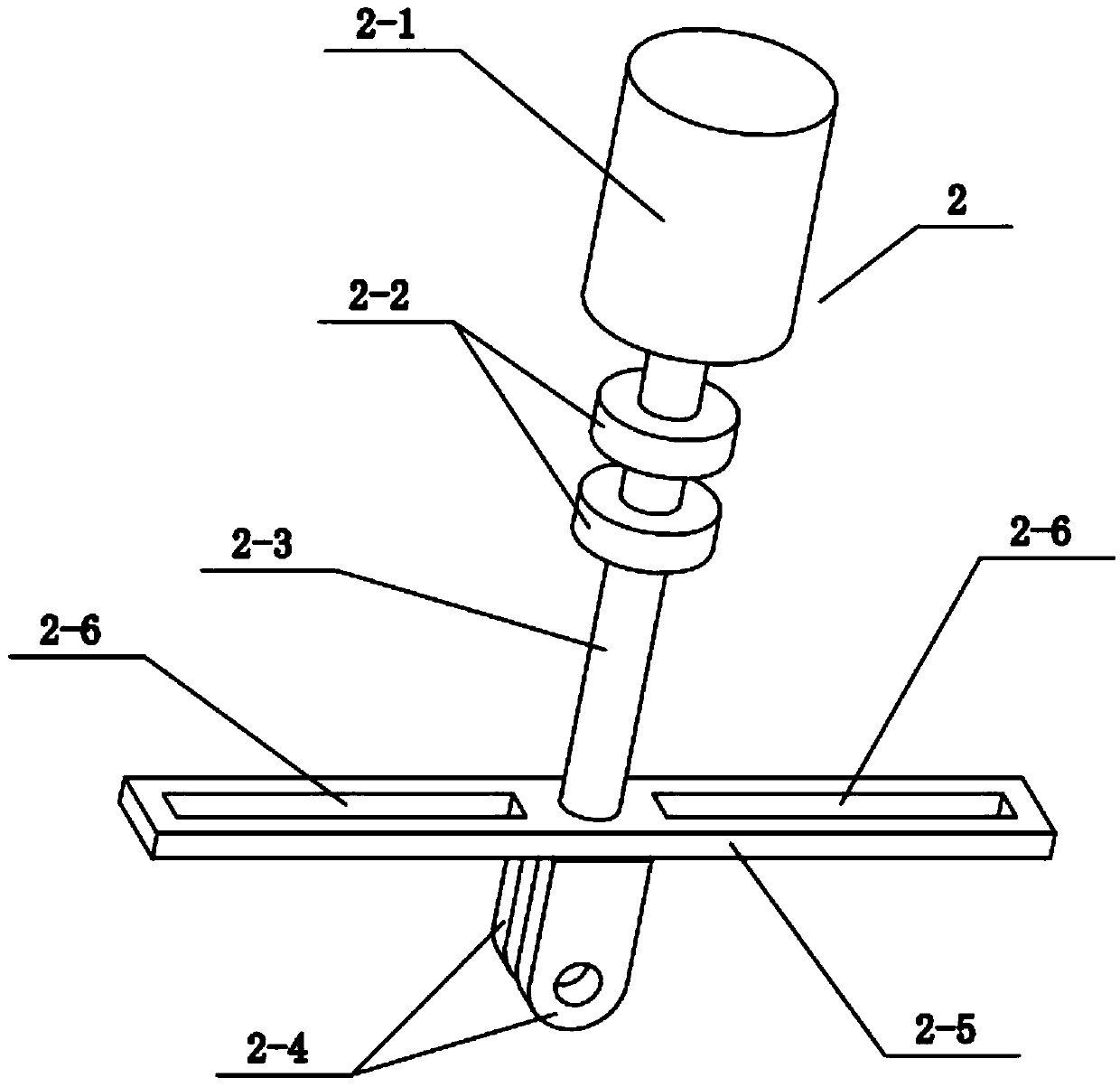
[0028] Combine below Figure 1-8Describe the present embodiment, described driving mechanism 2 comprises motor 2-1, limit ring 12-2, rotating shaft 2-3, hinge plate 2-4, horizontal hole bar 2-5 and rectangular hole 2-6, rotating shaft 2- The upper end of 3 is rotatably connected to the middle end of the beam bar 1-3, and the upper end of the rotating shaft 2-3 is fixedly connected with two limit rings I2-2, and the two limit rings I2-2 are connected with the upper and lower sides of the beam bar 1-3 respectively. The end faces are attached, the motor 2-1 is fixedly connected to the upper end of the beam rod 1-3, the output shaft at the lower end of the motor 2-1 is connected to the upper end of the rotating shaft 2-3 through a coupling, and the lower end of the rotating shaft 2-3 is fixedly connected to the The middle position of the horizontal hole rod 2-5, the left and right ends of the horizontal hole rod 2-5 are all provided with a rectangular hole 2-6, and the front and r...
PUM
 Abstract
Description
Claims
Application Information
 - R&D
- Intellectual Property
- Life Sciences
- Materials
- Tech Scout
- Unparalleled Data Quality
- Higher Quality Content
- 60% Fewer Hallucinations
Browse by: Latest US Patents, China's latest patents, Technical Efficacy Thesaurus, Application Domain, Technology Topic, Popular Technical Reports.
© 2025 PatSnap. All rights reserved.Legal|Privacy policy|Modern Slavery Act Transparency Statement|Sitemap|About US| Contact US: help@patsnap.com