
Positioning grinding structure for motorcycle exhaust cylinder

An exhaust pipe and motorcycle technology, which is applied to machine tools, grinders, grinding frames and other directions suitable for grinding the edge of workpieces, can solve the problems of poor grinding quality, shaking grinding effect, low grinding efficiency, etc., to avoid The effect of poor grinding effect, improved positioning effect and low manufacturing cost

Inactive Publication Date: 2019-04-16
重庆朔东汽车部件有限公司
View PDF5 Cites 0 Cited by
  • Summary
  • Abstract
  • Description
  • Claims
  • Application Information

AI Technical Summary

Problems solved by technology

[0002] As an integral part of the motorcycle, the motorcycle exhaust pipe plays a vital role. Due to the characteristic structure of the motorcycle, the existing motorcycle exhaust pipes are all exposed, so that the motorcycle exhaust pipe It is very easy to be deformed or scratched by collision. When the motorcycle exhaust tube is damaged, it needs to be repaired. After the repair, the outer surface of the motorcycle jettison tube has burrs or unevenness. The surface is polished. When the existing motorcycle repair shop polishes the motorcycle exhaust pipe, the method used is to directly place it on the ground and then position and polish the exhaust pipe by hand or foot. On the one hand, due to the use of Positioning is performed by hand or foot, which leads to poor positioning effect and is easy to shake during grinding, resulting in poor grinding effect; on the other hand, manual positioning increases the labor intensity of the operator and results in poor grinding quality; on the other hand, Grinding efficiency is low

Method used


Image

  • Positioning grinding structure for motorcycle exhaust cylinder
  • Positioning grinding structure for motorcycle exhaust cylinder
  • Positioning grinding structure for motorcycle exhaust cylinder

Examples


Embodiment Construction

[0025] Below in conjunction with accompanying drawing and embodiment the present invention will be further described:

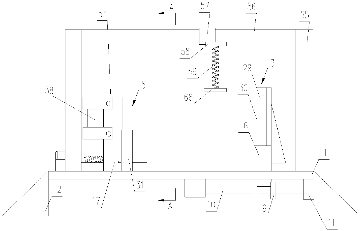
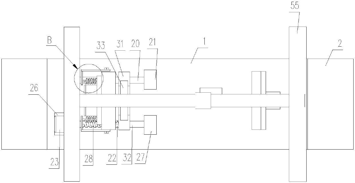
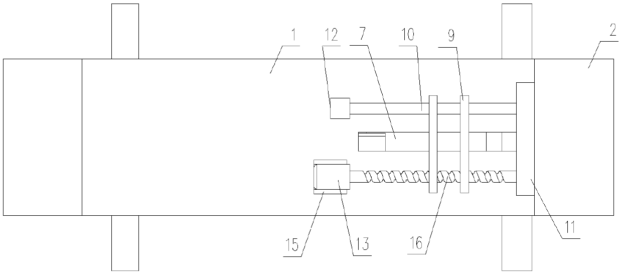
[0026] Such as Figure 1 to Figure 7 As shown, a positioning grinding structure for a motorcycle exhaust pipe includes a base plate 1, bases 2 are provided on both sides of the base plate 1, and a first positioning unit 3 and a second positioning unit 3 are arranged on the base plate 1. positioning unit 5;

[0027] The first positioning unit 3 includes a first sliding seat 6, an adjustment hole 7 is opened on the base plate 1, the first sliding seat 6 is located at the adjustment hole 7 and can be positioned along the length direction of the adjustment hole 7 Sliding, the upper part of the first sliding seat 6 is provided with a limiting member 8; the lower part of the first sliding seat 6 is provided with two parallel adjustment plates 9, and each of the adjustment plates 9 is slidably sleeved on the second On a guide rod 10, one end of the first guide rod...


PUM


Abstract

The invention discloses a positioning grinding structure for a motorcycle exhaust cylinder. The positioning grinding structure includes a base plate, bases are arranged on both sides of the base platecorrespondingly, a first positioning unit and a second positioning unit are arranged on the base plate; the first positioning unit includes a first sliding seat, an adjustment hole is formed in the base plate, the first sliding seat is located at the adjustment hole and can slide in the length direction of the adjustment hole, and a limiting part is arranged on the upper part of the first slidingseat; the lower part of the first sliding seat is provided with two adjustment plates parallel to each other, each adjustment plate slidably sleeves a first guiding rod, the other end of the guidingrod is connected with a second positioning seat, and a first positioning seat and the second positioning seat are connected with the bottom of the base plate. According to the positioning grinding structure for the motorcycle exhaust cylinder, on the one hand, the positioning effect is effectively improved, and the poor grinding effect caused by shaking during grinding is avoided; on the other hand, the grinding efficiency is improved while the labor intensity of operators is lowered; and the beneficial effects of simple structure, low manufacturing cost, convenient use and the like are achieved.

Description

technical field [0001] The invention relates to a positioning structure, in particular to a positioning grinding structure for motorcycle exhaust pipes. Background technique [0002] As an integral part of the motorcycle, the motorcycle exhaust pipe plays a vital role. Due to the characteristic structure of the motorcycle, the existing motorcycle exhaust pipes are all exposed, so that the motorcycle exhaust pipe It is very easy to be deformed or scratched by collision. When the motorcycle exhaust tube is damaged, it needs to be repaired. After the repair, the outer surface of the motorcycle jettison tube has burrs or unevenness. The surface is polished. When the existing motorcycle repair shop polishes the motorcycle exhaust pipe, the method used is to directly place it on the ground and then position and polish the exhaust pipe by hand or foot. On the one hand, due to the use of Positioning is performed by hand or foot, which leads to poor positioning effect and is easy to...

Claims


Application Information

Patent Timeline
Patent Type & Authority Applications(China)
IPC IPC(8): B24B9/00B24B41/02B24B47/22
CPCB24B9/00B24B41/02B24B47/22
Inventor 董世海肖作洪于道清
Owner 重庆朔东汽车部件有限公司
Learn More