
Product and waste separation device of plastic piece

A technology for separating equipment and plastic parts, applied in the field of injection molding parts production equipment, can solve the problems of low efficiency, heavy workload, low injection molding efficiency, etc., and achieve the effect of not easy to shift and low cost

Pending Publication Date: 2019-04-16
KUNSHAN CANSHENGHUI PRECISION MOLD
View PDF0 Cites 7 Cited by
  • Summary
  • Abstract
  • Description
  • Claims
  • Application Information

AI Technical Summary

Problems solved by technology

[0002] Some small-sized disc plastic parts are generally formed by injection molding process, and because the small-sized injection molding efficiency is not high, generally there are several products in a mold, and the flow channels between the products are connected, and the space corresponding to the flow channels after injection molding is completed. It will solidify into plastic waste, and the product needs to be cut off and separated from the plastic bracket. If it is manually repaired, the workload will be huge and the efficiency will be low

Method used


Image

  • Product and waste separation device of plastic piece
  • Product and waste separation device of plastic piece
  • Product and waste separation device of plastic piece

Examples


Embodiment Construction

[0032] Below in conjunction with specific embodiment, content of the present invention is described in further detail:

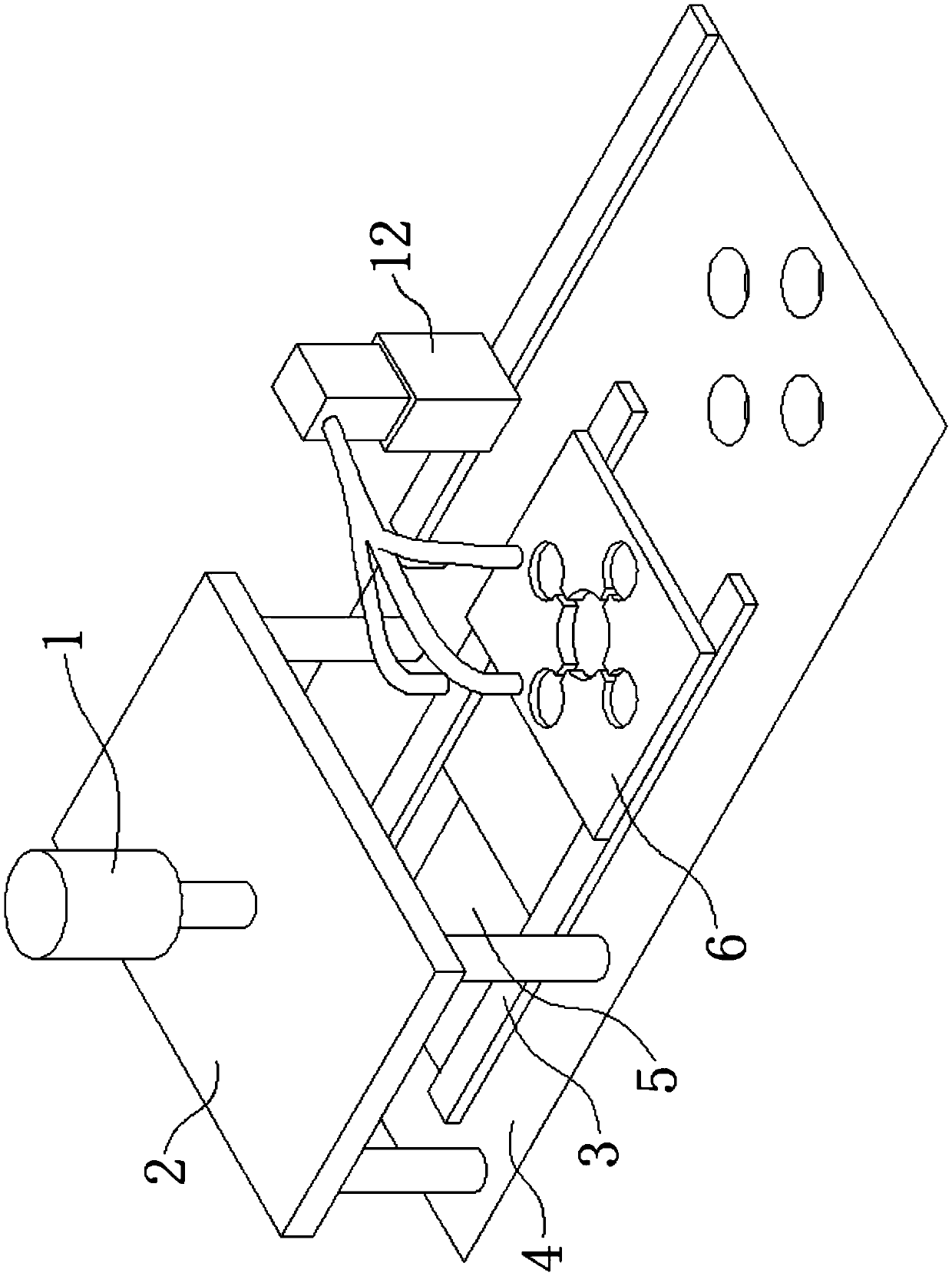
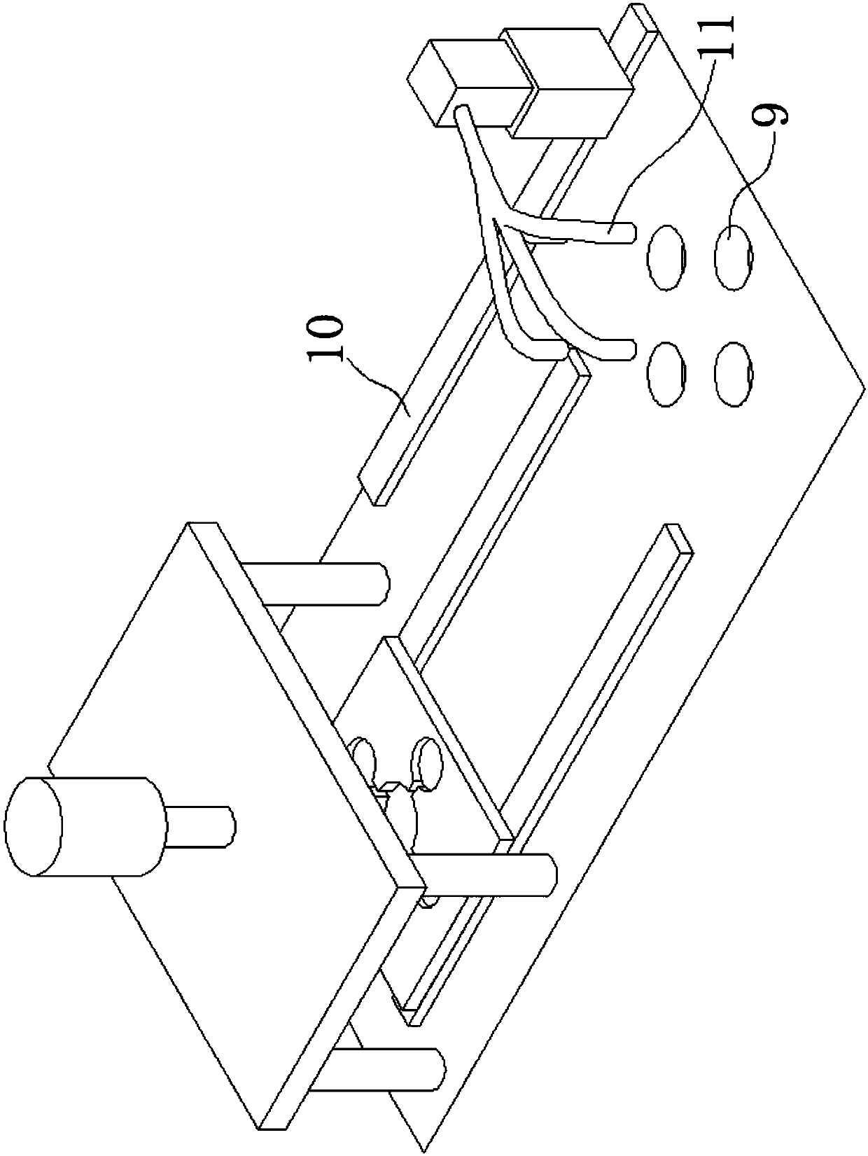
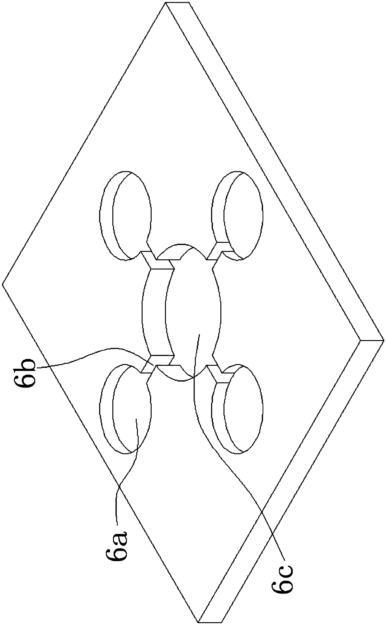
[0033] In order to achieve the purpose of the present invention, a product and waste separation equipment for plastic parts includes: a cutting mechanism with a cutter that cuts off from the junction of the product 7 and waste 8; a waste blanking mechanism with a workbench below the cutting mechanism 4. A waste material discharge opening 6 is provided directly below the cutter, and a sliding plate 6 is provided on the waste material discharge opening 5. The sliding plate 6 is provided with several product storage grooves 6a for accommodating products 7, and the product storage grooves 6a are in the shape of a ring array, the sliding plate 6 is equipped with a radial hole 6b for the waste material 8 to pass through and fall into the waste material discharge port 5, the radial hole 6b runs through the upper and lower surfaces of the sliding plate 6, and the hor...


PUM


Abstract

The invention discloses a product and waste separation device of a plastic piece. The device comprises a cutting mechanism, a waste material falling mechanism and a product falling mechanism, whereinthe cutting mechanism is provided with a cutter which can cut off a boundary line of products and waste materials; a working table is arranged below the cutting mechanism, a waste material falling port is formed right under the cutter, a sliding plate is arranged on the waste material falling port, a plurality of product containing tanks for containing products are formed in the sliding plate, theproduct containing tanks are arranged in an annular array, a radial hole allowing the waste materials to penetrate and fall into the waste material falling port is formed in the sliding plate, and all the product containing tanks are connected and gathered into one point in the horizontal direction of the radial hole; the sliding plate is connected to the working table through a horizontal sliding rail, the waste material falling port is formed in one end of the horizontal sliding rail, the other end of the horizontal sliding rail is provided with a product falling port, and the working tableis provided with a mechanical arm for transferring the products in the product containing tanks to the product falling port. By adopting the method disclosed by the invention, the separation of the products and the waste materials is realized efficiently, and the products are not easy to mix during material separation.

Description

technical field [0001] The invention relates to the field of production equipment for injection molded parts, in particular to a product and waste separation equipment for plastic parts. Background technique [0002] Some small-sized disc plastic parts are generally formed by injection molding process, and because the small-sized injection molding efficiency is not high, generally there are several products in a mold, and the flow channels between the products are connected, and the space corresponding to the flow channels after injection molding is completed. It will solidify into plastic waste, and it is necessary to cut off and separate the product from the plastic bracket. If it is manually repaired, the workload will be huge and the efficiency will be low. Contents of the invention [0003] The problem to be solved by the present invention is to provide a product and waste material separation equipment for plastic parts, which can efficiently realize the separation of...

Claims


Application Information

Patent Timeline
Patent Type & Authority Applications(China)
IPC IPC(8): B29C45/38B29C45/42
CPCB29C45/382B29C45/4225B29C2045/4233
Inventor 陈镇生
Owner KUNSHAN CANSHENGHUI PRECISION MOLD
Learn More