Spatial butt-joint and positioning device

A positioning device and space docking technology, applied in space vehicle docking devices, workpiece clamping devices, transportation and packaging, etc., can solve the problems of long time, low precision, complex docking technology, etc., and achieve simple structure, reliable docking, Reliable effect of docking positioning

Active Publication Date: 2019-04-16
WUHAN UNIV
View PDF5 Cites 5 Cited by
  • Summary
  • Abstract
  • Description
  • Claims
  • Application Information

AI Technical Summary

Problems solved by technology

[0003] The purpose of the present invention is to provide a space docking and positioning device, which solves the prob

Method used

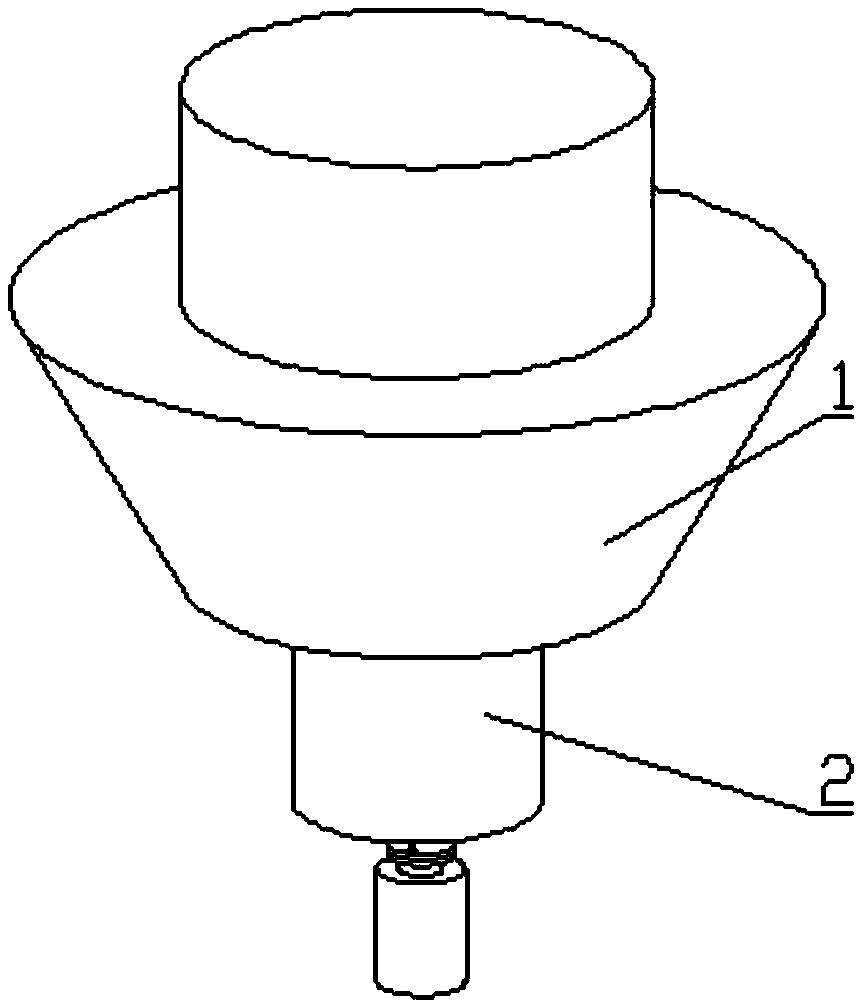
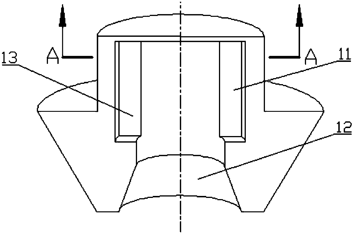
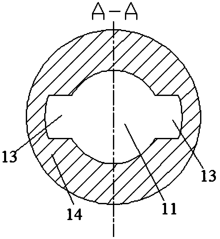

Image

  • Spatial butt-joint and positioning device
  • Spatial butt-joint and positioning device
  • Spatial butt-joint and positioning device

Examples


Example Embodiment

[0036] Example 1: Such as Image 6 As shown, one end of the pull rod 27 is connected to the shaft hole 233 at the lower end of the claw 23 by a movable pin, and the other end is connected to one end of the rope 28 by a movable pin. The other end of the rope 28 is fixed on the rope reel 29. The rope reel 29 is fixed on the motor A30, and the motor A30 is fixed on the positioning device main body 22 or the bracket on which the positioning device main body 22 is installed. The motor A30 can control the contraction and opening of the pawl 23 by forward and reverse rotation.

Example Embodiment

[0037] Example 2: Such as Figure 7 As shown, one end of the pull rod 27 is connected with the shaft hole 233 at the lower end of the claw 23 by a movable pin, and the other end is hinged with the upper end of the sleeve 31 through a connecting pin. The sleeve 31 is slidably connected or fixed with a fixed stroke of the sliding shaft 32 The sliding shaft 32 is a hollow shaft, and the bottom is fixed to the spiral sleeve 33. The spiral sleeve 33 and the screw 34 constitute a screw nut transmission mechanism. The bottom of the screw 34 is connected with a motor B35, and the motor B35 is fixed at On the positioning device body 22 or the bracket on which the positioning device body 22 is installed, the positive and negative rotation of the motor B35 can realize the contraction and expansion of the jaws. When the sleeve 31 and the sliding shaft 32 are slidingly connected, the two have a certain sliding stroke The sliding stroke is also the idle stroke generated by the movement of the...


PUM


Abstract

The invention discloses a spatial butt-joint and positioning device. The spatial butt-joint and positioning device comprises a butt-joint device and a positioning device, the butt-joint device comprises a butt-joint device body, a positioning device body is provided with a butt-joint hole, and at least one clamping groove is formed in the inner wall of the butt-joint hole; the positioning device comprises the positioning device body, an unlocking device and at least clamping jaw, the positioning device body is hollow inside, at least one window is formed in the side face of the upper portion of the positioning device body, the top of each clamping jaw is installed in the corresponding window through a rotary shaft, and a torsion spring is arranged on each rotary shaft, endows the corresponding clamping jaw with the trend of turning outwards; the unlocking device comprises pull rods the number of which corresponds to that of the clamping jaws, the top of each pull rod is hinged to the middle or the lower portion of the inner side of the corresponding clamping jaw, the lower ends of the pull rods are hinged together to form hinging points, when the hinging points are pulled downwardsfrom the interior of the positioning device body through external force, the clamping jaws can be pulled to be retracted into the windows, and unlocking is completed. The spatial butt-joint and positioning device is high in butt-joint speed, stable and reliable, and through the cooperation of the clamping jaws and the clamping grooves, circumferential positioning is achieved.

Description

Technical field [0001] The invention belongs to the field of space docking technology research, relates to a docking device, and in particular to a space docking positioning device. Background technique [0002] At present, the domestic and foreign spatial positioning and docking locking mainly uses multi-joint robotic arms to complete the capture and docking. However, the design of the robotic arms is complicated and the cost is higher; some use three-jaw docking mechanism, which is compared with multi-joint machinery. The structure of arm docking is simpler and easier to realize, but it is not easy to realize circumferential positioning. Therefore, it is necessary to provide a device that has a simple structure and can easily and reliably realize spatial docking and positioning. Summary of the invention [0003] The purpose of the present invention is to provide a space docking positioning device, which solves the problems of complicated docking technology, long time, low accur...

Claims


Application Information

Patent Timeline
IPC IPC(8): B64G4/00B64G1/64B25B11/00
CPCB25B11/00B64G1/64B64G1/646B64G4/00
Inventor 张志强罗学良毛晟伟肖华钱莉莉
Owner WUHAN UNIV
Why Eureka
Try Eureka