
Device for removing solids and method for removing solids in catalytic cracking oil slurry

A technology of catalytic cracking oil slurry and solid content, which is applied in the field of removal of solid content of catalytic cracking oil slurry and solid content removal device, which can solve the problem of poor separation effect, poor raw material properties, and long-term equipment failure Stable operation and other issues to achieve the effect of increasing the processing capacity and improving the separation efficiency

Active Publication Date: 2020-11-27
SINOPEC ENG GRP CO LTD
View PDF8 Cites 0 Cited by
  • Summary
  • Abstract
  • Description
  • Claims
  • Application Information

AI Technical Summary

Problems solved by technology

Compared with foreign countries, the raw material of catalytic cracking in domestic refineries is usually wax oil and a certain proportion of vacuum residue will be refined. The raw material properties are poor, resulting in a high content of solid particles and polar components in the oil slurry. Foreign electrostatic separation technology will inevitably lead to poor separation effect, and the equipment cannot run stably for a long period of time

Method used


Image

  • Device for removing solids and method for removing solids in catalytic cracking oil slurry
  • Device for removing solids and method for removing solids in catalytic cracking oil slurry
  • Device for removing solids and method for removing solids in catalytic cracking oil slurry

Examples


Embodiment 1

[0053] A method for removing solids in catalytic cracking oil slurry, comprising the following steps:

[0054] The first step is to exchange the heat of the catalytic cracking oil slurry to 200°C;

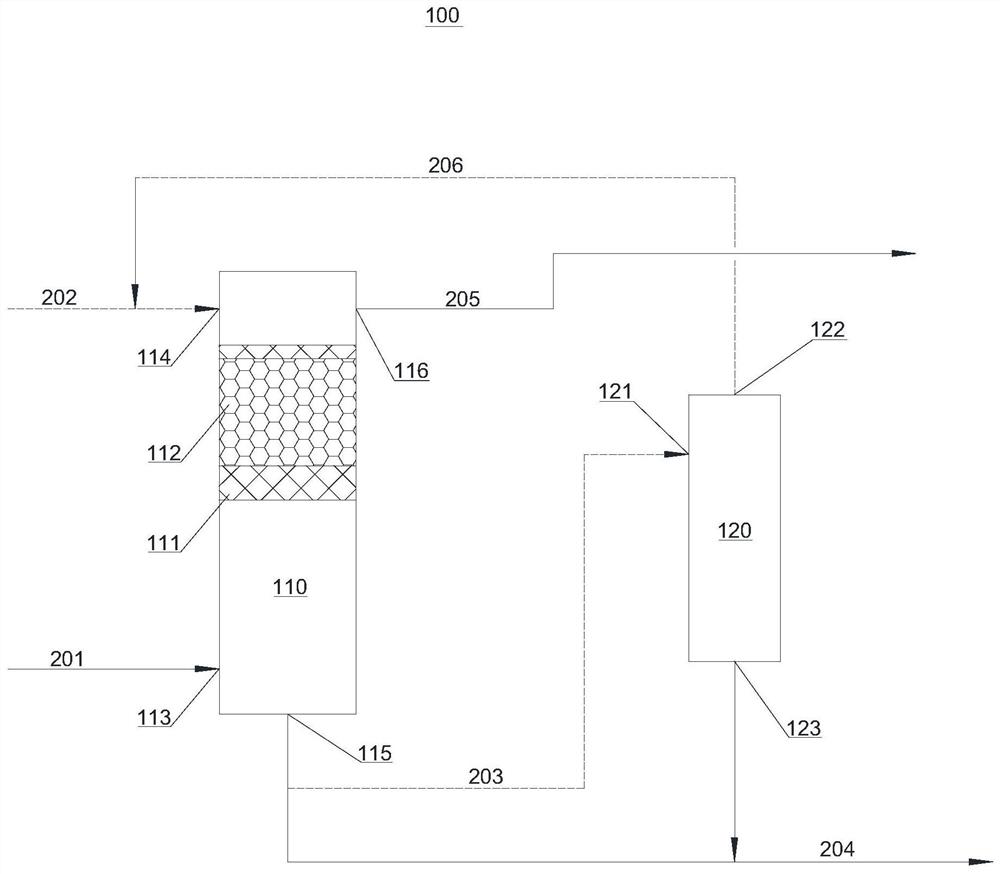
[0055] In the second step, the oil slurry after heat exchange is transported to the electrostatic separation tank for desolidification treatment. The lower part of the electrostatic separation tank is the electrostatic coalescence part, and its electric field strength is a DC electric field of 8000V / cm; the upper part of the electrostatic separation tank is an electrostatic adsorption part with modified glass beads as the adsorption filler, and its electric field strength is a DC electric field of 5000V / cm; After being treated in an electrostatic separation tank for 2 hours, purified oil slurry and heavy oil slurry are obtained; the heavy oil slurry is directly thrown out;

[0056] The third step is to use naphtha as the backwash solvent to backwash the electrostatic coalescence t...

Embodiment 2-6

[0059] The removal method of the catalytic cracking oil slurry solid content that embodiment 2-6 provides is basically the same as embodiment 1, difference is:

Embodiment 2

[0060] In Example 2, the catalytic cracking oil slurry was heat-exchanged to 80°C;


PUM

PropertyMeasurementUnit
strengthaaaaaaaaaa
strengthaaaaaaaaaa
strengthaaaaaaaaaa

Abstract

The invention relates to the technical field of oil slurry purification treatment and provides a solid matter removal device and a method for removing catalytic cracking oil slurry solid matter. The solid matter removing device includes an electrostatic separation tank, wherein the electrostatic separation tank is internally provided with an electrostatic coalescence layer and an electrostatic adsorption layer, and the electrostatic coalescence layer is located below the electrostatic adsorption layer. According to the method for removing catalytic cracking oil slurry solid matter, heat-exchanged catalytic cracking oil slurry is introduced into the solid matter removing device and is subjected to solid removal treatment, and purified oil slurry and heavy oil slurry are obtained. A part ofsolid particles is pre-removed by electric field coalescence pretreatment and then is subjected to advanced treatment under an electrostatic adsorption effect, it can be achieved that the oil slurry directly enters an electrostatic adsorption zone for treatment after electrostatic coalescence, and accordingly stepwise removal of the solid particles is achieved. The redispersion of solid particlesdue to fluid flowing can be effectively avoided, the separation efficiency and treatment capacity of the device are improved, and large-scale industrial continuous production is facilitated.

Description

technical field [0001] The invention relates to the technical field of oil slurry purification treatment, in particular to a device for removing solids and a method for removing solids in catalytic cracking oil slurry. Background technique [0002] Catalytic cracking oil slurry is a by-product of the catalytic cracking (FCC) process, and its utilization is greatly limited due to its high content of solid particles (mainly catalyst particles and metal ions). Currently, most refineries sell FCC slurry as a blending component for heavy fuel oil. When the catalytic cracking oil slurry is used as fuel oil, it will cause many problems such as the wear of the furnace nozzle and the accumulation of dust on the surface of the furnace tube, which will affect the smooth operation of the furnace. Moreover, the use of catalytic oil slurry as fuel oil greatly reduces the utilization value of catalytic oil slurry. Catalytic cracking oil slurry contains a large amount of polycyclic aromat...

Claims


Application Information

Patent Timeline
Patent Type & Authority Patents(China)
IPC IPC(8): C10G32/02
CPCC10G32/02
Inventor 崔新安蒋兴家唐应彪李春贤申明周李朝法
Owner SINOPEC ENG GRP CO LTD
Learn More