
Heat shaping device used for wall plate cover shell

A heat setting and cover technology, applied in heat treatment furnaces, furnace types, heat treatment equipment, etc., can solve the problem that the diameter of the inner hole of the flange cannot reach the size of the inner hole of the flange, the diameter of the inner hole of the flange is difficult to maintain, and the wall plate cover cannot be put into use. Use and other issues to achieve the effect of convenient processing and improved yield

Active Publication Date: 2019-04-16
WUHAN MARINE MACHINERY PLANT
View PDF5 Cites 2 Cited by
  • Summary
  • Abstract
  • Description
  • Claims
  • Application Information

AI Technical Summary

Problems solved by technology

[0003] Since the wall panel shell has square grooves on the outer wall and the flange, it is difficult to keep the diameter of the inner hole of the flange on the end face of the petal-shaped wall panel shell to meet the design requirements of the flange.
At the same time, the wall panel shell usually needs to be heat-treated to shape it. However, after the heat treatment, the wall panel shell will cool and shrink, causing the petals on the petal-shaped wall panel shell to shrink and deform. If the wall panel shell cannot be controlled Shrinkage and deformation will cause the diameter of the inner hole of the flange to fail to meet the design requirements, making the wall panel shell unable to be put into use and scrapped

Method used


Image

  • Heat shaping device used for wall plate cover shell
  • Heat shaping device used for wall plate cover shell
  • Heat shaping device used for wall plate cover shell

Examples


Embodiment Construction

[0025] In order to make the object, technical solution and advantages of the present invention clearer, the implementation manner of the present invention will be further described in detail below in conjunction with the accompanying drawings.

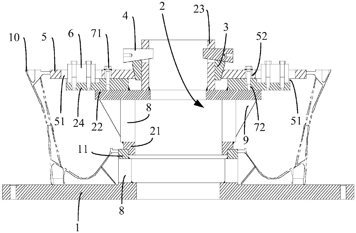
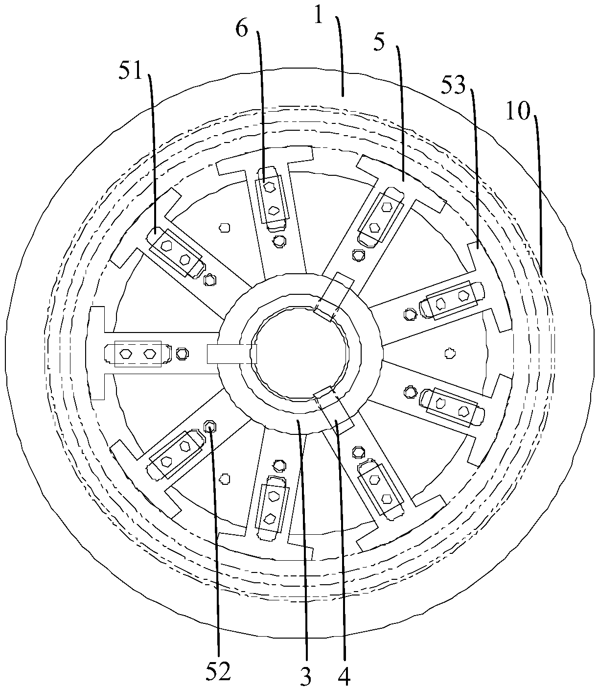
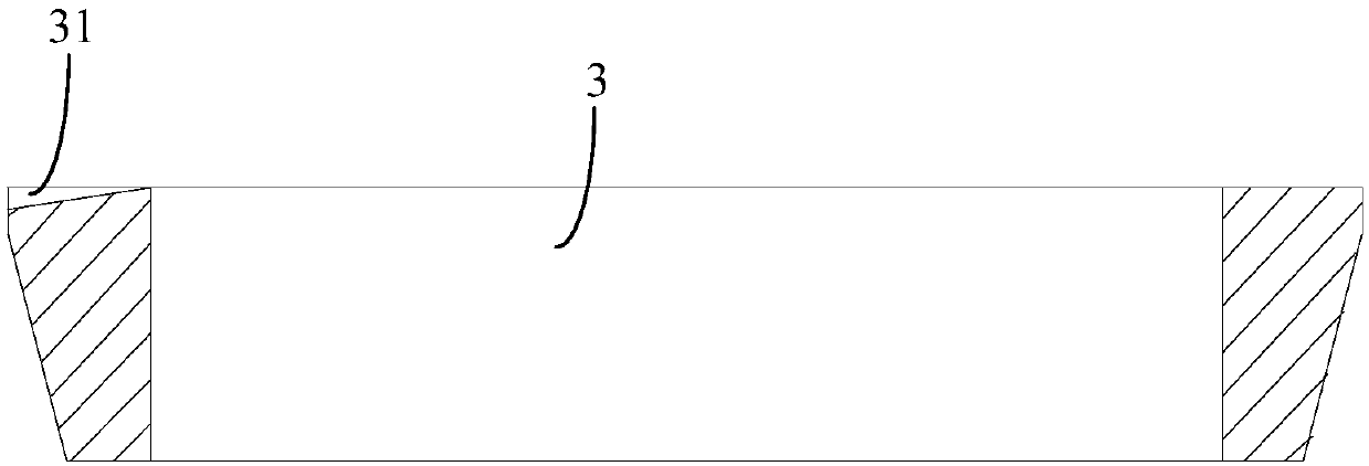
[0026] figure 1 It is a structural schematic diagram of a heat setting device for a wall panel shell provided by an embodiment of the present invention, figure 2 It is a top view of a heat setting device for a wall panel shell provided by an embodiment of the present invention. Such as figure 1 , 2 As shown, the heat setting device includes: a positioning chassis 1 , a positioning bracket 2 , a positioning cone ring 3 , a positioning cone block 4 , a positioning expansion block 5 and a guide block 6 . One side of the positioning chassis 1 is provided with a housing positioning ring 11 coaxially arranged with the positioning chassis 1, and the positioning bracket 2 includes: installing a positioning ring 21, a support plate 22, a mo...


PUM


Abstract

The invention discloses a heat shaping device used for a wall plate cover shell. The heat shaping device comprises a positioning chassis, a positioning support, a position adjusting conical ring, a position adjusting conical block, a positioning expansion block and a guide block; the positioning chassis and a cover shell positioning ring are coaxially arranged, the positioning support comprises amounting positioning ring, a supporting disc, a mounting cylinder and a mounting ring, the mounting positioning ring is coaxially arranged on one side face of the supporting disc, the mounting ring and the mounting cylinder are coaxially arranged on the other side face of the supporting disc, the mounting positioning ring is inserted on the cover shell positioning ring, the outer diameter of the cover shell positioning ring is the same with the inner diameter of a flange at one end of the wall plate cover shell, one side face of the position adjusting conical block is a slope, and is matched with the groove face of a groove in the end face of the position adjusting conical block, the mounting cylinder is sleeved with the position adjusting conical ring, the end face of one end of the positioning expanding block is attached to the outer wall face of the position adjusting conical ring, and the end face of the other end of the positioning expanding block is attached to the inner wall face of the flange on the other end of the wall plate cover shell. At the machining treatment period of the flange on the wall plate cover shell, the inner hole diameter size is kept at the designed required size.

Description

technical field [0001] The invention relates to the technical field of mechanical processing, in particular to a heat-setting device for a wall panel casing. Background technique [0002] There are a large number of thin-walled parts in gas turbine parts, which have the characteristics of thin wall thickness, poor rigidity, and high machining accuracy, and the wall plate casing is one of them. Flanges are usually provided on both ends of the wall panel casing, and before the wall panel casing is put into use, a plurality of circumferentially distributed square grooves need to be opened on the outer wall and the flange, so that the wall panel casing forms a petal-like structure. [0003] Since the wall panel casing has a square groove on the outer wall and the flange, it is difficult to keep the diameter of the flange inner hole on the end face of the petal-shaped wall panel casing to meet the design requirements of the flange. At the same time, the wall panel shell usually ...

Claims


Application Information

Patent Timeline
IPC IPC(8): C21D9/00
CPCC21D9/0068
Inventor 肖威姜耘哲王臻熊永钊
Owner WUHAN MARINE MACHINERY PLANT
Learn More