

A kind of preparation method of far ultraviolet high reflection mirror
A high reflective mirror, far ultraviolet technology, applied in the field of preparation of far ultraviolet high reflective mirror, can solve the problems of large difference, easy oxidation of Al film surface, limited materials, etc.
- Summary
- Abstract
- Description
- Claims
- Application Information
AI Technical Summary
Problems solved by technology
Method used
Image

Examples
Embodiment 1
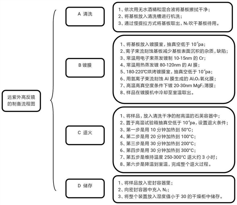
[0046] 1. With Al+MgF 2 For example, the film preparation process is mainly carried out from two aspects of coating and annealing. The specific steps are as follows:
[0047] (1) Coating: The substrate is ultrasonically cleaned and then cleaned with N 2 Dry the substrate for use; after the substrate is placed in the coating chamber, the vacuum is lowered to less than 10 -4 pa; use an ion beam with a voltage of 450V, a current of 600mA, an oxygen flow rate of 0 sccm, and an argon gas flow rate of 20 sccm to etch the substrate for about 10 minutes. The etching technology can reduce the impurities and defects deposited on the substrate surface and improve the substrate surface. Quality; use electron beam evaporation at room temperature (parameter 140mA current) to evaporate 10-15nm Cr at a rate of 7-10A / s to increase the adhesion of the substrate to the Al film; use thermal evaporation at room temperature by applying a current of 450mA , heat and melt the Al particles in the tu...
PUM
| Property | Measurement | Unit |
|---|---|---|
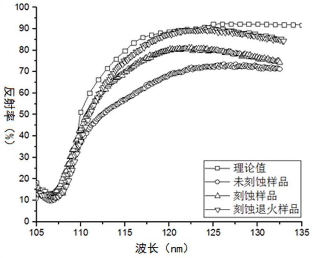
| reflectance | aaaaa | aaaaa |
| reflectance | aaaaa | aaaaa |
Abstract
Description
Claims
Application Information