Bag grouting well wall sealing structure

A bagging and grouting technology, which is applied in infrastructure engineering, construction, etc., can solve the problems that the backfill water-stopping effect is not easy to control, the grouting effect cannot be tested, and the well wall is gushing water, etc., so as to improve the well wall water-stopping effect, Guarantee the effect of well wall water stop and fast well wall water stop effect

Pending Publication Date: 2019-04-16
中交哈尔滨地铁投资建设有限公司 +1
View PDF0 Cites 4 Cited by
  • Summary
  • Abstract
  • Description
  • Claims
  • Application Information

AI Technical Summary

Problems solved by technology

The existing technology has the following defects: a. The gap between the well wall and the hole wall is small, and the water-stop effect of backfilling is not easy to control, which may easily lead to poor water-stop effect due to backfilling of the well wall. The irrigation process is prone to water gushing on the well wall; b. Using backfill clay balls to stop ...

Method used


Image

  • Bag grouting well wall sealing structure
  • Bag grouting well wall sealing structure
  • Bag grouting well wall sealing structure

Examples


Embodiment

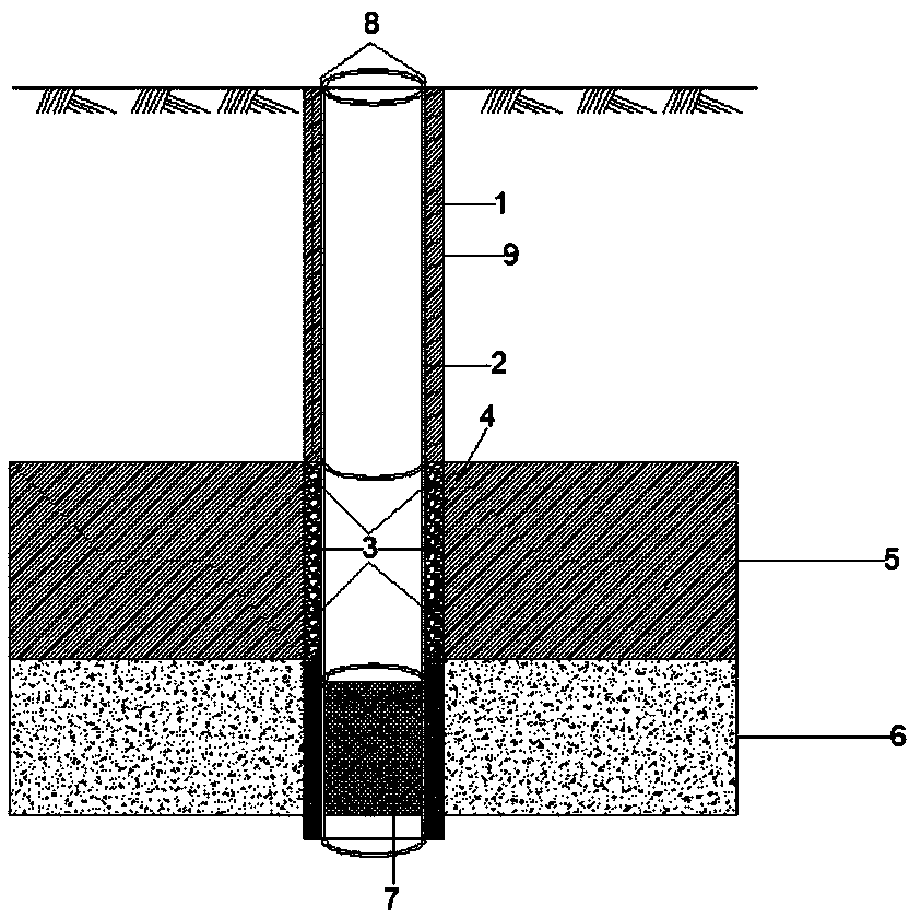
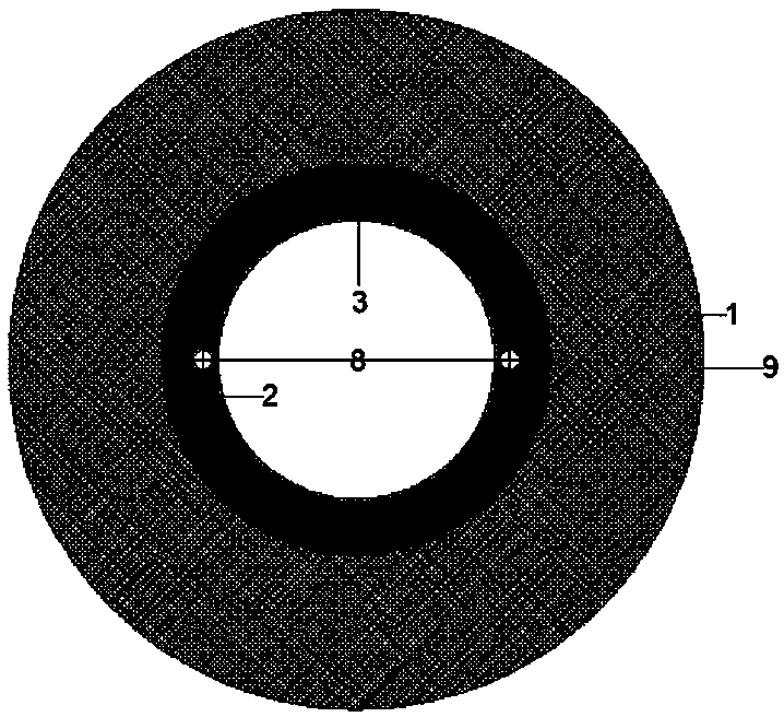
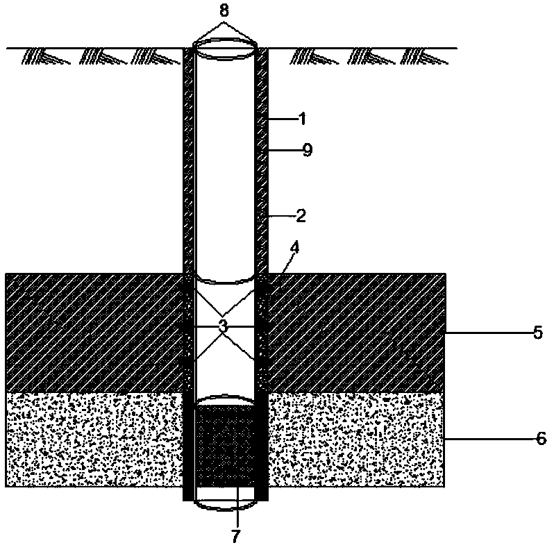
[0019] Embodiment: A bag grouting well wall water-stop structure, characterized in that it includes a bag 3 and a grouting pipe 8; the bag 3 is fixed on the outer wall of the well pipe 2; the bag 3 is connected to the grouting Pipe 8; after grouting in the pocket 3, the pocket 3 expands until the hole wall 9 is fully in contact with the original soil body or expanded and embedded in the original soil body.

[0020] The bladder 3 is fixedly arranged on the outer wall of the well pipe 2 in layers.

[0021] Between the outer wall of the well pipe 2 and the hole wall 9 is a packing layer 4 .

[0022] The packing layer 4 includes a filter material layer and a water-stop layer.

[0023] The lower part of the well pipe 2 is backfilled with filter material corresponding to the aquifer 6 to form a filter material layer, and the upper part of the filter material layer is backfilled with clay 1 corresponding to the water-resistant layer 5 to form a water-stop layer.

[0024] The pouch ...


PUM


Abstract

The invention provides a bag grouting well wall sealing structure. The structure is characterized by comprising a bag and a grouting pipe; the bag is fixed on the outer wall of a well pipe; the bag isconnected with the grouting pipe, and a grouting port of the grouting pipe extends to the ground; after the bag is grouted, the bag is expanded to a hole wall original soil body to be in full contactwith the original soil body or is expanded to be embedded in the original soil body. The bag grouting well wall sealing structure has the advantages that 1, the operation is simple, the effect is reliable, the purpose of well wall sealing can be achieved quickly; 2, the well wall sealing effect can be maximally improved, and the effect of resisting confined groundwater head pressure of the well wall can be improved, thereby ensuring the sealing effect of the well wall a relief well or recharge well.

Description

technical field [0001] The invention relates to a well wall water-stop structure of a pressure-relief well or a reinjection well, in particular to a bag-grouting well-wall water-stop for improving the water-stop strength of a pressure-relief well or a recharge well wall and realizing quick water stop The structure is used in deep foundation pit decompression and dewatering engineering and recharge engineering. Background technique [0002] In the prior art, high-quality clay balls of a certain thickness are backfilled in the relief well or the reinjection well wall as a water-stopping measure for the well wall, and the well wall grouting is implemented in the case of relatively high requirements. The existing technology has the following defects: a. The gap between the well wall and the hole wall is small, and the water-stop effect of backfilling is not easy to control, which may easily lead to poor water-stop effect due to backfilling of the well wall. The irrigation proce...

Claims


Application Information

Patent Timeline
IPC IPC(8): E02D15/04E02D19/06
CPCE02D15/04E02D19/06
Inventor 刘运生张强刘宝许李会良聂善军梁宇张力林森斌毛喜云杲亚强王静冯恒北
Owner 中交哈尔滨地铁投资建设有限公司
Why Eureka
Try Eureka