An electronically controlled compensation two-way proportional flow valve

A proportional flow valve and compensation valve technology, applied in fluid pressure actuating devices, servo motor components, mechanical equipment, etc., can solve problems such as control valves that are not suitable for large flow, complex structures, etc., to improve flow control accuracy, overcome The effect of poor controllability and good steady-state load characteristics

Active Publication Date: 2021-01-08
TAIYUAN UNIV OF TECH
View PDF8 Cites 0 Cited by
  • Summary
  • Abstract
  • Description
  • Claims
  • Application Information

AI Technical Summary

Problems solved by technology

However, the shortcoming of this valve is that the structure is relatively complicated, and it is not suitable for large flow control valves.

Method used


Image

  • An electronically controlled compensation two-way proportional flow valve
  • An electronically controlled compensation two-way proportional flow valve
  • An electronically controlled compensation two-way proportional flow valve

Examples


Embodiment 1

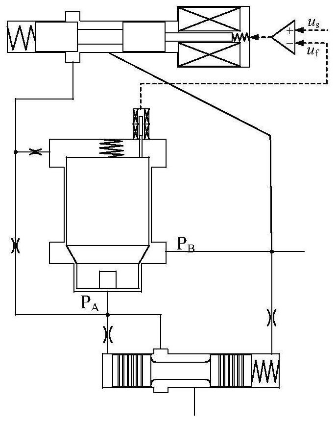
[0036] An electronically controlled and compensated two-way proportional flow valve, comprising a proportional pilot valve 1, a main valve 6 and a first displacement sensor 10;

[0037] Such as Figure 4 As shown, the proportional pilot valve includes the pilot spool 2, the first proportional electromagnet 3, the pilot valve spring 4, the pilot valve body 5, the pilot valve oil inlet A 2 and pilot valve outlet B 2 ;

[0038] Such as Figure 5 As shown, the main valve includes the main valve core 7, the main valve sleeve 8, the main valve return spring 9, the main valve oil inlet P A , main valve oil outlet P B and main valve control chamber P C ; The first displacement sensor 10 is installed on the main valve core 7 to detect the displacement of the main valve core 7; it is characterized in that it also includes an electronic pressure compensation valve 11;

[0039] The electronic pressure compensation valve 11 is a pressure compensation valve controlled by a proportiona...

Embodiment 2

[0050] The second embodiment of an electronically controlled compensation two-way proportional flow valve of the present invention is the same as the first embodiment in terms of structural composition and connection relationship, and the difference is that an electro-hydraulic pressure compensation valve 12 is used.

[0051] Such as Figure 9 As shown, the electro-hydraulic pressure compensation valve 12 includes a displacement sensor 13, a compensation valve body 15, a compensation valve core 16, a spring 17, an oil inlet A, an oil outlet B, and the first control chamber P F , the second control chamber P E and the third control chamber P G The compensation valve core 16 is arranged in the compensation valve body 15, one end of the spring 17 acts on the left end surface C of the compensation valve core 16, and the other end acts on the compensation valve body 15, and forms the first control chamber P with the compensation valve core 16 F , the displacement sensor 13 is ins...


PUM


Abstract

The invention provides an electric control compensation two-way proportional flow valve. The electric control compensation two-way proportional flow valve adopts a novel electronic pressure compensation valve or an electric-hydraulic pressure compensation valve; an oil outlet B1 of the electronic pressure compensation valve or the electric-hydraulic pressure compensation valve communicates with anoil inlet PA of a main valve and a first control cavity PF of the electronic pressure compensation valve or the electric-hydraulic pressure compensation valve; and an oil outlet PB of the main valvecommunicates with a second control cavity PE of the electronic pressure compensation valve or the electric-hydraulic pressure compensation valve. The novel elements of the electronic pressure compensation valve and the electric-hydraulic pressure compensation valve are designed; an electronic control unit is adopted to control and detect the positions of compensation valve elements, so that the closed-loop control of the compensation valve elements and the continuous adjustment of compensation pressure differences are realized, the flow control precision of the whole valve is improved, and theanti-load change flow adjusting rigidity is improved; and the electric control compensation two-way proportional flow valve has the advantages of simple structure, good dynamic characteristics and high precision of stable flow control.

Description

technical field [0001] The invention belongs to a two-position two-way proportional flow valve, in particular to an electronically controlled compensation two-way proportional flow valve. Background technique [0002] As the core component of the electro-hydraulic control system of major mechanical equipment, the two-way proportional flow valve can continuously control the flow of hydraulic actuators and is widely used in marine engineering, railway tunnels, aerospace, nuclear power and other fields. By the valve flow equation It can be seen that the flow through the proportional flow valve is not only related to the opening area A of the valve port, but also affected by the change of the pressure difference Δp at both ends of the valve port. [0003] To eliminate load variation effects such as figure 1 As shown, the traditional flow valve connects a pressure compensating valve in series at the inlet or outlet of the proportional throttle valve to maintain a constant pres...

Claims


Application Information

Patent Timeline
Patent Type & Authority Patents(China)
IPC IPC(8): F15B13/02
CPCF15B13/02F15B13/026
Inventor 权龙王波王翔宇葛磊郝云晓杨敬
Owner TAIYUAN UNIV OF TECH
Why Eureka
Try Eureka