Sealing cushion ring and forming method thereof
A technique for sealing gaskets and forming methods, which is applied in the direction of engine sealing, engine components, mechanical equipment, etc., can solve the problems of increasing production costs, etc., and achieve the effects of easy production, meeting the needs of use, and good sealing effect
Inactive Publication Date: 2019-04-16
KUSN ZHONGDI MATERIALS TECH
5 Cites 0 Cited by
AI-Extracted Technical Summary
Problems solved by technology
[0003] Due to the large cavity of the power battery pack, the perimeter of the foamed silicone gasket required for sealing the interface of the cavity is great...
Method used
According to the sealing gasket 1 of the embodiment of the present invention, it adopts the form of bonding, which effectively saves production cost on the one hand, prevents the waste of raw materials, and is convenient for production at the same time, and the overall performance of the sealing gasket 1 obtained in this way is similar to that of Compared with the sealing gasket 1 prepared by integral molding, they all have better sealing performance and meet the actual use requirements.
But, the quantity of protrusion 238 is not the more the better, although it can increase the adhesive contact area, but the mechanical capacity of the joint in the later stage is not good, and it is not convenient for processing and splicing and bonding simultaneously, therefore, optionally , the number of protrusions 238 is one, and the setting of one protrusion 238 can effectively reduce the difficulty of processing, and at the same time, it is convenient for splicing and bonding in the later stage, and the stability of the connection is the best.
By bonding at least two components 2 successively end to end to form a ring, the whole process is simple and controllable, and simultaneously the materials required for the ring structure avoid the generation of internal waste in die cutting, effectively reducing production costs and improving Productivity.
Optionally, at least two components 2 are bonded in sequence from end to end, and the end face of each component 2 can be a slope or a plane, for example, in two adjacent components 2, one component 2 has a first slope (not shown in the figure), the other has a second slope (not shown) corresponding to the first slope, the first slope is connected to the second slope, and is fixed by the adhesive layer at the same time, through the first slope and the second slope It is set to effectively increase the contact area between the two components 2, wherein, for better fixing effect, the adhesive layer composed of adhesive is coated on the first slope and the second slope. In addition, the sealing gasket 1 according to the embodiment of the present invention also has the following additional technical features:
That is, the junction of the first c...
Abstract
The invention discloses a sealing cushion ring and a forming method thereof, and relates to the technical field of sealing pieces. The sealing cushion ring includes at least two assemblies, and at least two assemblies are bonded to form a closed ring shape in sequence from heads to tails. According to the sealing cushion ring, the structure is simple, the cost is low, and the sealing effect is good. The forming method of the sealing cushion ring comprises the steps that at least two assemblies are obtained, and the assemblies are bonded to form the ring shape in sequence from the heads to thetails. According to the forming method, the method is especially suitable for the forming of large-sized sealing cushion rings, and the operation can be controlled, and the waste of materials is prevented effectively meanwhile.
Application Domain
Engine seals
Technology Topic
CushionEngineering
Image
Examples
- Experimental program(1)
Example Embodiment
[0046] The embodiments of the present invention are described in detail below. Examples of the embodiments are shown in the accompanying drawings, wherein the same or similar reference numerals represent the same or similar elements or elements with the same or similar functions. The embodiments described below with reference to the drawings are exemplary, and are only used to explain the present invention, but should not be understood as limiting the present invention.
[0047] The sealing gasket 1 according to the embodiment of the first aspect of the present invention will be described below with reference to the drawings.
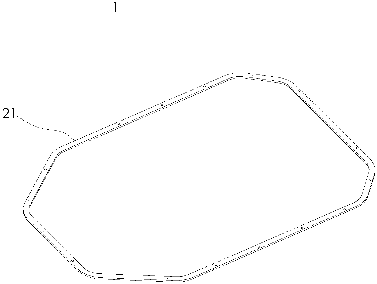
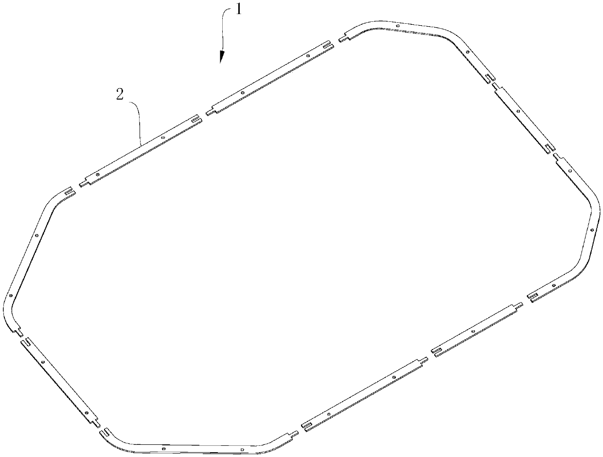
[0048] Such as figure 1 with figure 2 As shown, the sealing gasket 1 according to the embodiment of the present invention includes: at least two components 2, and the at least two components 2 are bonded in order from end to end to form a closed ring.
[0049] Specifically, at least two are, for example, two, three, five, ten, etc. The specific number of the components 2 is not as large as possible, and it is set reasonably according to the molding equipment and material properties.
[0050] According to the sealing gasket 1 of the embodiment of the present invention, it adopts the form of bonding, on the one hand, it effectively saves the production cost, prevents the waste of raw materials, and is easy to manufacture. At the same time, the overall performance of the sealing gasket 1 made by this method and the integral molding preparation Compared with the sealing gaskets 1, all have better sealing performance and meet the actual use requirements.
[0051] Among them, the width and thickness of each component 2 can be the same, that is, the cross-sectional area of any position of the annular sealing gasket 1 is the same, and the cross-sectional shape is also the same, where the cross-section refers to the direction perpendicular to the axis of the component 2 Cross section, width refers to the maximum distance between the inner ring surface and the outer ring surface of the sealing gasket 1. The width and thickness of each component 2 can be different and can be set according to actual needs.
[0052] Wherein, the shape of the sealing gasket 1 may be a circular ring, a rectangular ring or an irregular geometric shape, and those skilled in the art can make a selection according to actual needs.
[0053] The size of the sealing gasket 1 is relatively large. Optionally, the circumference of the sealing gasket 1 is greater than 4m, and the thickness is 2mm-20mm, for example, the thickness is 2mm, 5mm, 10mm, 15mm or 20mm. Under this condition, the sealing gasket 1 of the above structure Among them, the connection effect between the components 2 is better.
[0054] Optionally, the shape of the sealing gasket 1 is approximately a rectangular frame shape. Specifically, the sealing gasket 1 includes a first direction and a second direction, the first direction and the second direction are perpendicular, and the two ends of the sealing gasket 1 are symmetrical along the first direction. The two ends of the sealing gasket 1 in the second direction are arranged asymmetrically, and the projections of the two ends of the sealing gasket 1 in the second direction on the horizontal plane are similar to an isosceles trapezoid. Optionally, the connection of each component 2 is smoothly transitioned.
[0055] Optionally, the shape of the sealing gasket 1 can be changed according to actual application scenarios.
[0056] Optionally, in order to ensure a better connection effect, the length of each component 2 is 120-600mm, and the width is 10mm-100mm. It should be noted that the sum of the length of each component 2 forms the circumference of the sealing gasket 1. Long, where the width refers to the maximum distance between the inner ring surface and the outer ring surface of the sealing gasket 1.
[0057] The shape of each component 2 is a strip, and the projection of each component 2 on the horizontal plane can be linear, curved, or a combination of the two, etc., which is not specifically limited here.
[0058] Optionally, at least two components 2 are bonded in turn from end to end, and the end surface of each component 2 can be a bevel or a flat surface. For example, in two adjacent components 2, one component 2 has a first bevel (not shown in the figure). (Shown), the other has a second inclined surface (not shown) corresponding to the first inclined surface, connects the first inclined surface and the second inclined surface, and is fixed by an adhesive layer at the same time, by setting the first inclined surface and the second inclined surface, The contact area between the two components 2 is effectively increased. In order to achieve a good fixing effect, the adhesive layer composed of adhesive is coated with the first inclined surface and the second inclined surface. In addition, the sealing gasket 1 according to the embodiment of the present invention has the following additional technical features:
[0059] Optionally, each component 2 is provided with a positioning hole 21 for positioning the sealing ring using a screw or the like in a subsequent actual practical process. Optionally, the positioning holes 21 are arranged equidistantly along the circumferential direction of the sealing gasket 1. Wherein, the positioning hole 21 is provided in the thickness direction of the component 2. Wherein, when the component 2 is bonded to form the sealing gasket 1, the thickness direction of the component 2 is parallel to the axial direction of the sealing gasket 1.
[0060] According to some embodiments of the present invention, any two adjacent components 2 described above are configured as a first component 23 and a second component 24, the first component 23 is provided with a first connecting portion, and the second component 24 is provided with a second connecting portion , The first connecting portion and the second connecting portion are plug-connected, and an adhesive layer (not shown in the figure) is formed at the mating position, and the adhesive layer is used to fix the adjacent first component 23 and second component 24.
[0061] That is, the adjacent first component 23 and the second component 24 are not only fixed by the adhesive layer, but at the same time, the first connection part and the second connection part are plug-in connection to further strengthen the first component 23. The stability of the connection with the second component 24.
[0062] However, it should be noted that for the sealing gasket 1 obtained by bonding at least two components 2, the joint between any two adjacent components 2 is flush with the surface of the sealing gasket 1.
[0063] For an alternative embodiment, see image 3 , The plug-in connection is: the first component 23 has a first end surface 231, the first connecting portion is a first protruding portion 233 provided on the first end surface 231, the second connecting portion has a second end surface 241, and the second end surface 241 is provided with There is a second protrusion 243. A second recess 245 is formed between the second protrusion 243 and the second end surface 241. The second recess 245 is a second link part that cooperates with the first protrusion 233. A first recessed portion 235 is formed between the protruding portion 233 and the first end surface 231, that is, the first recessed portion 235 and the second protruding portion 243 are matched and fixed by the adhesive layer, and the second recessed portion 245 is connected to the first The protrusion 233 is matched and fixed by the adhesive layer.
[0064] That is, the connection between the first connecting portion and the second connecting portion forms a zigzag shape, which increases the contact area on the one hand, and on the other hand has a certain degree for the first component 23 and the second component 24, and further improves the overall integrity and Sealing performance.
[0065] Specifically, the first protruding portion 233 has a third end surface 236 on a side away from the first end surface 231, the first protruding portion 233 has a first connecting surface, and the first end surface 231 and the third end surface 236 pass through the first connecting surface. Connected, the side of the second protrusion 243 away from the second end surface 241 has a fourth end surface 246, the second protrusion 243 has a second connection surface, and the second end surface 241 and the fourth end surface 246 are connected by the second connection surface, An adhesive layer is provided between the first end surface 231 and the fourth end surface 246, and an adhesive layer is provided between the second end surface 241 and the third end surface 236.
[0066] By having an adhesive layer between the first end surface 231 and the fourth end surface 246, and an adhesive layer between the second end surface 241 and the third end surface 236, two adjacent first components 23 and second components 24 are effectively fixed.
[0067] Optionally, there is an adhesive layer between the first connection surface and the second connection surface.
[0068] Further improve the stability of the connection, and at the same time the entire connection is in a state of being closed by the adhesive layer to prevent the entry of air, etc., and the sealing effect is better.
[0069] In another alternative embodiment, see Figure 4 , The plug-in connection is as follows: the first connecting portion is provided with a protrusion 238, and the second connecting portion is provided with a groove 248 matching the protrusion 238.
[0070] Compared with the Z-shape, the mating manner of the protrusion 238 and the groove 248 in the plug-in connection has a larger adhesive contact area, which is beneficial to consolidate the adhesive sealing effect and the strength of the adhesive.
[0071] Among them, it should be noted that the number of protrusions 238 is at least one, for example, 1, 2, 3, or 4, etc., and the number of grooves 248 corresponds to the protrusions 238 in a one-to-one manner, so that the protrusions 238 are effectively combined. It is embedded in the corresponding groove 248, and the connection is fixed by an adhesive layer.
[0072] However, the number of protrusions 238 is not as good as possible. Although it can increase the bonding contact area, the mechanical ability of the later connection is not good, and it is not convenient for processing and splicing. Therefore, optionally, the protrusions The number of 238 is one, and the setting of one protrusion 238 can effectively reduce the difficulty of processing, at the same time, it is convenient for later splicing and bonding, and the stability of the joint is the best.
[0073] Wherein, the cross-sectional shape of the protrusion 238 can be one or a combination of a rectangle, a circle, an ellipse, a trapezoid, or an irregular shape, etc., which is not limited here, and those skilled in the art can design according to actual needs. set.
[0074] Optionally, the end surface on the side of the first connecting portion where the protrusion 238 is provided may be a flat surface or an inclined surface, which is not specifically limited herein.
[0075] According to some embodiments of the present invention, the cross-sectional area of the first connecting portion is one-third to one-half of the cross-sectional area of the component 2, and the cross-sectional area of the second connecting portion is one-third of the cross-sectional area of the component 2. One to one half.
[0076] Through the limitation of the cross-sectional area, the stability of the connection between the first connection part and the second connection part is improved, and the mechanical performance of the connection part will not be affected, and the sealing performance of the sealing ring will not be affected. Wherein, the cross section of the first connecting portion refers to the cross section of the first connecting portion located perpendicular to the axis of the first connecting portion, and the cross section of the second connecting portion refers to the cross section of the second connecting portion located perpendicular to the axis of the second connecting portion.
[0077] Optionally, the length of the first connecting portion is 5mm-30mm, and the length of the second connecting portion is 5mm-30mm, which facilitates the bonding operation and ensures the bonding quality without affecting the overall physical and mechanical properties of the material.
[0078] It should be noted that under the above conditions, both ends of the first component 23 can be set as the first connection portion, or one end of the first component 23 is the first connection portion, and the other end is the second connection portion. Those skilled in the art can make settings according to actual conditions.
[0079] According to some embodiments of the present invention, the material of each of the above-mentioned components 2 includes at least one of rubber, foamed silica gel and silica gel, and the two adjacent components 2 are made of silica gel products and/or those with a Shore hardness of less than 40A. Fixed glue bonding.
[0080] Optionally, the material of each of the aforementioned components 2 is foamed silica gel, that is, the sealing gasket 1 obtained in the present invention is a foamed silicone sealing gasket 1.
[0081] Silicone products and fixing glue with a Shore hardness of less than 40A not only have a good fixing effect for the component 2, but also have a certain elasticity and toughness after fixing to prevent the joint of two adjacent components 2 from cracking.
[0082] The molding method of the sealing gasket 1 according to the embodiment of the second aspect of the present invention includes:
[0083] At least two components 2 are obtained, and the at least two components 2 are sequentially bonded end to end to form a ring shape.
[0084] By bonding at least two components 2 end to end in sequence to form a ring shape, the entire process is simple and controllable, and at the same time, the materials required for the ring structure are prevented from being generated internally during die cutting, effectively reducing production costs and improving production efficiency.
[0085] See Figure 5 In the molding method of an optional embodiment shown in the present invention, before the at least two components 2 are sequentially bonded end to end, it further includes coating at least one end of each component 2 with an adhesive. For example, both ends are coated with an adhesive, and then at least two components 2 are sequentially bonded end to end to form a ring shape using the adhesive.
[0086] The following methods can also be adopted to bond at least two components 2 end to end in sequence: at least two components 2 are spliced end to end in sequence to form a ring shape, and an adhesive is injected at each splicing position, so that two adjacent components 2 are adhered according to the Adhesive for fixation.
[0087] Wherein, the material of each component 2 includes at least one of rubber, foamed silica gel, and silica gel, and two adjacent components 2 are bonded by silica gel products and/or fixing glue with a Shore hardness of less than 40A.
[0088] Optionally, the way to obtain at least two components 2 is: according to the specific sealing gasket 1, decompose it into at least two blanks, and punch and die cut the blanks into components 2, which effectively saves the existing integrated molding. It avoids the generation of internal waste during the die cutting of the required materials.
[0089] Punching die-cutting equipment uses flat knife molds, which can be rubber molds, wood molds, aluminum molds or iron molds. Those skilled in the art can make a selection according to actual needs, and will not be detailed here.
[0090] The foamed silicone gasket 1 with a circumference of 4m (such as figure 1 (Shown) is compared with the existing market-produced integrally formed foamed silicone gasket 1 with a circumference of 4m, and it is found that the molding method of the foamed silicone gasket 1 provided by the present invention is compared to integrally formed, regardless of the component 2 Whether the connection is provided with the first connection part and the second connection part can effectively reduce the waste material discharged after the foamed silicone sealing gasket 1 is formed, and the reduction rate is greater than or equal to 80%.
[0091] The foamed silicone gasket 1 (the overall shape is like figure 1 As shown, the connection is like Figure 4 As shown, the circumference is 4m, as the test group 1) and the unspliced foamed silicone gasket (the overall shape is as figure 1 As shown, as the test group 2), physical and mechanical properties were compared, and the results are shown in Table 1.
[0092] Table 1 Comparison of mechanical properties
[0093]
[0094] The comparison between the two shows that the quality of the adhesive splicing foamed silica gel in test group 1 is not much different from the original quality of test group 2, and the tensile strength increases after bonding and splicing. At the same time, the connection of component 2 is as image 3 As shown, the circumference is 4m, and the overall shape is figure 1 The sealing gasket 1 shown after bonding and splicing is used as the test group 3, and the mechanical properties of the test group 3 are checked by the above method. The quality of the test group 3 is not much different from the original quality of the test group 2. The tensile strength increased, but the tensile strength was lower than the test group 1. At the same time, it adopts the form of direct end bonding without the first connection part and the second connection part, and the obtained circumference is 4m, and the overall shape is like figure 1 The sealing gasket 1 shown after bonding and splicing is used as test group 4. The overall performance of test group 4 using bonded and spliced foamed silicone is slightly better than test group 2. The tensile strength after bonding and splicing increases, but the increase is smaller.
[0095] Test groups 1, 2, 3, and 4 are used to seal power battery packs, respectively, and the sealing effect and service life of the four are equivalent.
[0096] In summary, the sealing gasket molding method provided by the embodiment of the present invention is particularly suitable for the molding of large-size sealing gaskets. It not only has controllable operation, but also effectively prevents material waste. At the same time, the resulting sealing gasket has a simple structure and low cost.
[0097] The above are only the preferred embodiments of the present invention and are not used to limit the present invention. For those skilled in the art, the present invention can have various modifications and changes. Any modification, equivalent replacement, improvement, etc., made within the spirit and principle of the present invention should be included in the protection scope of the present invention.
PUM


Description & Claims & Application Information
We can also present the details of the Description, Claims and Application information to help users get a comprehensive understanding of the technical details of the patent, such as background art, summary of invention, brief description of drawings, description of embodiments, and other original content. On the other hand, users can also determine the specific scope of protection of the technology through the list of claims; as well as understand the changes in the life cycle of the technology with the presentation of the patent timeline. Login to view more.
Similar technology patents
Magnetic cooling apparatus and control method thereof
Owner:SAMSUNG ELECTRONICS CO LTD
Electronic cigarette and a wireless charging device for the same
Owner:KIMREE HI TECH
Sputtering method and sputtering apparatus
Owner:OSAKA VACUUM +1
Dual-Drivetrain of Power-Assist Vehicle
Owner:CHOU WEN CHENG
Classification and recommendation of technical efficacy words
- Simple structure
- low cost
Sharing system for air-conditioning coat
Owner:QINGDAO HAIER AIR CONDITIONER GENERAL CORP LTD
Temperature-fixing dehumidifying air conditioner and control method thereof
Owner:HAIER GRP CORP +1
Nozzle transmission mechanism for 3D printer and 3D printer with same
Owner:J H TECH ELECTRONICS GZ LTD
Feeding device of sorter of batteries plate
Owner:NANJING NORMAL UNIVERSITY
Emergency parachuting device and method for multiple-rotor unmanned aerial vehicle
Owner:SOUTH CHINA AGRI UNIV +1
Method, apparatus and article for microfluidic control via electrowetting, for chemical, biochemical and biological assays and the like
Owner:KECK GRADUATE INST OF APPLIED LIFE SCI
System and method for transmitting wireless digital service signals via power transmission lines
Owner:NEXTEL COMMUNICATIONS
System and method for determination of position
Owner:STEELE CHRISTIAN
Antenna device and method for attaching the same
Owner:NEC CORP