Device and method for measuring optical parameter field of dispersion medium based on time-frequency optical information fusion

A technology of dispersive medium and optical parameters, applied in the field of optical imaging, can solve the problems of low reconstruction accuracy of optical parameter fields and less measurement data, and achieve the effect of solving reconstruction problems and accurate reconstruction problems.

Active Publication Date: 2019-04-16
HARBIN INST OF TECH
View PDF5 Cites 6 Cited by
  • Summary
  • Abstract
  • Description
  • Claims
  • Application Information

AI Technical Summary

Benefits of technology

This patented describes a technique called Time-Frequency Optical Imaging (TFI) that combines two techniques - spectral analysis and spatial resolution. It involves measuring the scattered rays caused when transmitting electromagnetic waves within a scattering material at different angles or directions. Based upon this data, it analyzes how well they are distributed throughout its volume without being affected by other materials around them. Overall, TF allows researchers to study complex phenomena such as turbidity diffusion over large areas while also providing valuable insights into their physical properties like refractivity coefficients.

Problems solved by technology

This patents describes different techniques used during studying dispersions where there are multiple particle distributions within each space. These include measurements from microscopic observation devices like scanning electron microscopy that measure scattered intensity patterns at specific points along the surface of the material being studied. However, these conventional approaches have limitations when trying to achieve accurate results due to factors including limited resolution caused by coherence between neighboring particles' radiance fields, difficulty in calculating optimal parameters associated with this method, complexity involved in analyzing waveforms, and difficulties in accurately determining the properties of the materials under study without destructively testing them.

Method used


Image

  • Device and method for measuring optical parameter field of dispersion medium based on time-frequency optical information fusion
  • Device and method for measuring optical parameter field of dispersion medium based on time-frequency optical information fusion
  • Device and method for measuring optical parameter field of dispersion medium based on time-frequency optical information fusion

Examples


specific Embodiment approach 1

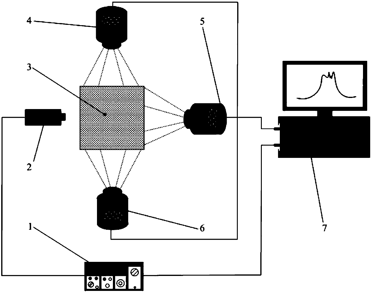
[0039] The device for measuring the optical parameter field of a diffuse medium based on time-frequency optical information fusion in this embodiment, such as figure 1 As shown, the measuring device includes a laser controller 1, a laser head 2, a dispersive medium 3, a group of microlens array light field cameras 4 and a data acquisition and processing system 7;

[0040] One end of the laser controller 1 is connected to the laser control signal output end of the laser head 2, and the other end of the laser controller 1 is connected to the data acquisition and processing system 7; The signal output terminal is connected; wherein, all the microlens array light field cameras 4 are on the same plane as the laser head 2, and the laser head 2 and a group of microlens array light field cameras 4 are evenly distributed around the dispersive medium 3;

[0041] Moreover, when the laser light emitted by the laser head 2 enters the dispersive medium 3 , the laser light emitted by the laser...

specific Embodiment approach 2

[0042] The difference from Embodiment 1 is that, in the device for measuring the optical parameter field of a diffuse medium based on time-frequency optical information fusion in this embodiment, the number of the microlens array light field cameras 4 is the same as the shape of the diffuse medium 3. Adaptation, when the shape of the dispersion medium 3 is cylindrical, the number of microlens array light field cameras 4 is 2, which are respectively arranged on the boundary surface side formed by the two ends of the dispersion medium 3; when the shape of the dispersion medium 3 is In the case of a regular prism, the number of microlens array light field cameras 4 is the number of boundary surfaces of the diffuse medium 3 minus 1.

specific Embodiment approach 3

[0043] Different from the second specific embodiment, the device for measuring the optical parameter field of a diffuse medium based on time-frequency optical information fusion in this embodiment, such as figure 1 As shown, when the shape of the dispersion medium 3 is a square, the number of microlens array light field cameras 4 is three, including the first microlens array light field camera 4, the second microlens array light field camera 5 and the second microlens array light field camera 5. Three microlens array light field cameras 6, one end of the laser controller 1 is connected to the laser control signal output end of the laser head 2, and the other end of the laser controller 1 is connected to the data acquisition and processing system 7; the signal input end of the data acquisition and processing system 7 is simultaneously Connect with the signal output end of the first microlens array light field camera 4, the second microlens array light field camera 5, and the thi...


PUM


Abstract

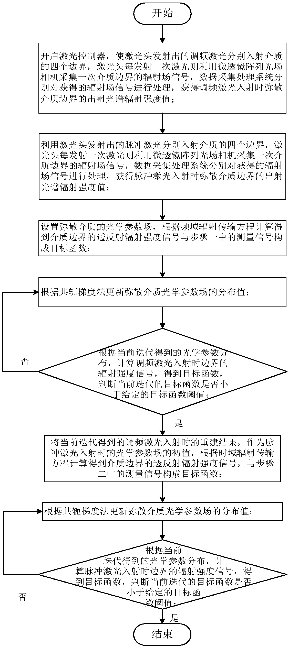
The invention relates to a device and method for measuring the optical parameter field of a dispersion medium based on time-frequency optical information fusion, which belongs to the technical field of optical imaging and solves the problems of small amount of acquired measurement data and low reconstruction precision of the optical parameter field when the reconstruction is performed by using measurement signals of a single model during the simultaneous reconstruction of the absorption and scattering coefficient distribution of the dispersion medium. The method comprises the steps of respectively acquiring radiation intensity information on boundaries of the dispersion medium in each direction under the action of frequency modulation laser and pulse laser by using a light field camera with a microlens array, preliminarily acquiring a reconstructed image of the optical parameter field inside the medium under the frequency domain model through simulating the infrared radiation transmission process in the dispersion medium under the action of frequency modulation laser, serving as an initial optical parameter field of the time domain model, and obtaining the internal structure of thedispersion medium through simulating the infrared radiation transmission process inside the dispersion medium under the action of pulse laser. The high-precision reconstruction of the optical parameter field can be completed by using the method of the invention.

Description


Claims


Application Information

Patent Timeline
Owner HARBIN INST OF TECH
Why Eureka
Try Eureka