Pump part machining and flaw detection equipment

A technology of parts and equipment, which is applied in the field of pump parts processing flaw detection equipment, can solve problems such as low cleaning efficiency, waste of water resources, and environmental damage, and achieve the effects of improving work efficiency, saving water resources, and reducing occupancy

Active Publication Date: 2019-04-16
ANHUI YINLONG PUMP VALVE
View PDF6 Cites 5 Cited by
  • Summary
  • Abstract
  • Description
  • Claims
  • Application Information

AI Technical Summary

Problems solved by technology

[0002] After the pump parts are processed, some dust and other debris may be attached to them. If manual cleaning is used, not only the cleaning efficiency is low and the cleaning effect is not good, but also the labor burden is increased, and the processing cost is increased. After processing, flaw detection is usually required to test the quality of parts. The fixed setting of the flaw detector makes it difficult to carry out the flaw detection operation of the parts, and it is impossible to realize the comprehensive flaw detection of the parts; use mechanized equipment to clean and dry the parts, spray water The position of the head and drying head is usually fixed, and the position of the parts is usually fixed, so that the parts cannot be fully and fully cleaned and dried; the direct discharge of cleaning water will not only cause environmental damage, but also cause Waste of water resources; due to the different types of parts, the fixed positions of the cleaning head, drying head, and flaw detector make it inconvenient to clean, dry, and flaw detect parts of different types; Place the parts that need to be processed on the rack, and then carry out the processing operation. The placement of the parts will not only take a lot of time, but also cause the equipment to stop running intermittently, reducing the processing efficiency of the equipment; In the processing and production process, various equipment are usually required to realize processing, cleaning, drying, and flaw detection. The use of different equipment will not only increase the cost, but also occupy a lot of limited space in the factory. Therefore, a processing of pump parts is now required Flaw detection equipment

Method used


Image

  • Pump part machining and flaw detection equipment
  • Pump part machining and flaw detection equipment
  • Pump part machining and flaw detection equipment

Examples


Embodiment 1

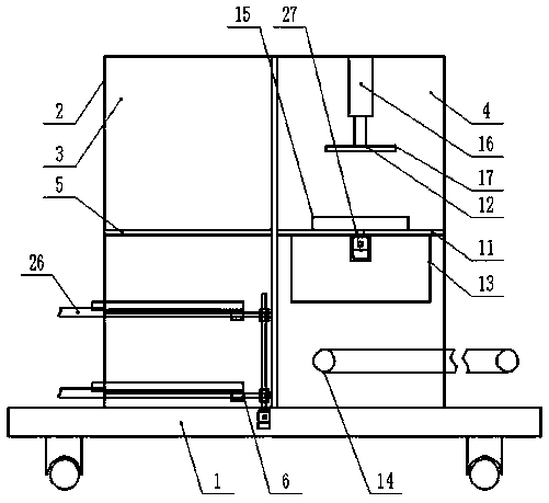
[0017] Embodiment 1: see figure 1 , figure 2 , image 3 , Figure 4 , Figure 5 Now, a kind of flaw detection equipment for pump parts processing provided by the present invention will be described, including machine base 1, universal wheels provided at the four corners of the bottom end of machine base 1 and a processing flaw detection box provided at the middle of the upper end of machine base 1 2. The middle part of the processing flaw detection box 2 is provided with a partition along the vertical direction, and the partition divides the inner cavity of the processing flaw detection box 2 into a left processing chamber 3 and a right cleaning flaw detection chamber 4. The middle part of the inner cavity of the left processing chamber 3 is provided with a first support plate 5, the upper end of the first support plate 5 is provided with intelligent processing equipment for pump parts, and the lower end of the inner cavity of the left processing chamber 3 is provided with...

Embodiment 2

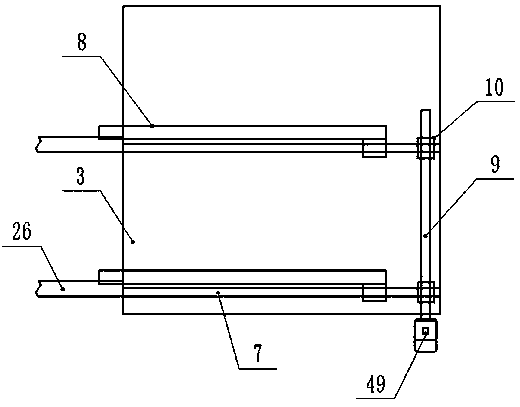
[0018] Example 2: see figure 1 , figure 2 , the present invention provides a description of a pump parts processing flaw detection equipment, the number of the first screw 7 is two, the first screw 7 is respectively set in the left processing chamber 3 cavity width direction The middle part, and one end of the first screw 7 is movably connected with the partition respectively, the connection ends of the first screw 7 are respectively covered with the worm wheel 10, and the worm 9 is set corresponding to the position of the worm wheel 10 and The worm 9 and the worm wheel 10 cooperate with each other for transmission. The inner cavity of the base 1 is provided with a first rotating motor 49 and the output shaft of the first rotating motor 49 is connected to the bottom end of the worm 9 through a coupling. Shaft connection, the bottom of the side end of the feeding plate 8 close to the position of the worm wheel 10 and the first screw rod 7 are respectively provided with a firs...

Embodiment 3

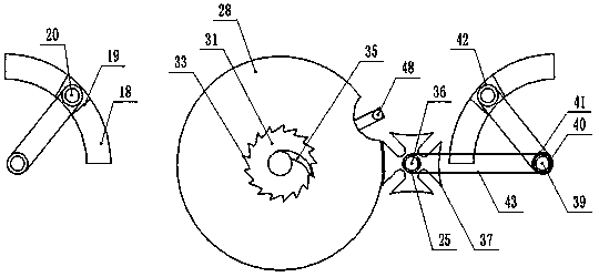
[0019] Embodiment 3: see figure 1 , image 3 , Figure 4 Now, a kind of flaw detection equipment for pump parts processing provided by the present invention will be described. The second support plate 11 has a water permeable hole and the water permeable hole is connected with the inner cavity of the water collection tank 13 through a pipeline. The middle part of the second support plate 11 lower end is provided with a second rotating motor 27, and the disc-shaped placing frame 15 comprises a first disc-shaped placing frame 28 and a second disc-shaped placing frame 29, and the first disc-shaped placing frame The position of frame 28 is movably arranged, and described second disc-shaped placing frame 29 is movably arranged on the upper end of described first disc-shaped placing frame 28, and the middle part of the lower end of described second disc-shaped placing frame 29 has a circular groove 30 , the middle part of the first disk-shaped placement frame 28 has a circular thr...


PUM


Abstract

The invention discloses pump part machining and flaw detection equipment. The pump part machining and flaw detection equipment comprises a machine base, universal wheels and a machining and a flaw detection box body, wherein the inner cavity of the machining and flaw detection box body is divided into a left side machining chamber and a right side cleaning and flaw detection chamber through a partition plate, a first supporting plate is arranged in the middle of the left side machining chamber cavity, a pump part intelligent machining device is arranged at the upper end of the first supportingplate, a feeding mechanism is arranged at the lower end of the left side machining chamber cavity, the feeding mechanism is composed of first screw rods, feeding plates, a worm and worm wheels, the right side cleaning and flaw detection chamber is provided with a second supporting plate, a cleaning and flaw detection assembly, a water collecting tank and a belt conveyor, and the cleaning and flawdetection assembly is composed of a disc shaped placing frame, an air cylinder, a pressing plate, an arc-shaped groove, an arc-shaped seat, a second screw rod, a sliding seat, a water spraying head,a drying head, an ultrasonic flaw detector and a transmission assembly.

Description

technical field [0001] The invention relates to the field of production of pump parts, in particular to a processing flaw detection equipment for pump parts. Background technique [0002] After the pump parts are processed, some dust and other debris may be attached to them. If manual cleaning is used, not only the cleaning efficiency is low and the cleaning effect is not good, but also the labor burden is increased, and the processing cost is increased. After processing, flaw detection is usually required to test the quality of parts. The fixed setting of the flaw detector makes it difficult to carry out the flaw detection operation of the parts, and it is impossible to realize the comprehensive flaw detection of the parts; use mechanized equipment to clean and dry the parts, spray water The position of the head and drying head is usually fixed, and the position of the parts is usually fixed, so that the parts cannot be fully and fully cleaned and dried; the direct discharg...

Claims


Application Information

Patent Timeline
Patent Type & Authority Applications(China)
IPC IPC(8): G01N29/04B23P23/04
CPCB23P23/04G01N29/04
Inventor 吴辉王清龙汪云唐宗清孟金华王文汇徐俊东
Owner ANHUI YINLONG PUMP VALVE
Why Eureka
Try Eureka