
Laser emitting device

A technology of laser emission and laser transmitter, which is applied in the direction of measuring device, utilization of re-radiation, and re-radiation of electromagnetic waves, etc., can solve the problem of low data refresh frequency, and achieve the effect of improving data refresh frequency and simple overall structure.

Active Publication Date: 2019-04-16
广州市慧建科技有限公司
View PDF22 Cites 4 Cited by
  • Summary
  • Abstract
  • Description
  • Claims
  • Application Information

AI Technical Summary

Problems solved by technology

In the existing laser scanning triangulation positioning systems, the transmitter emits a laser beam, and the target positioning data is refreshed once every rotation cycle, the data refresh frequency is low, and the laser beam can only detect targets at a certain height

Method used


Image

  • Laser emitting device
  • Laser emitting device
  • Laser emitting device

Examples


Embodiment Construction

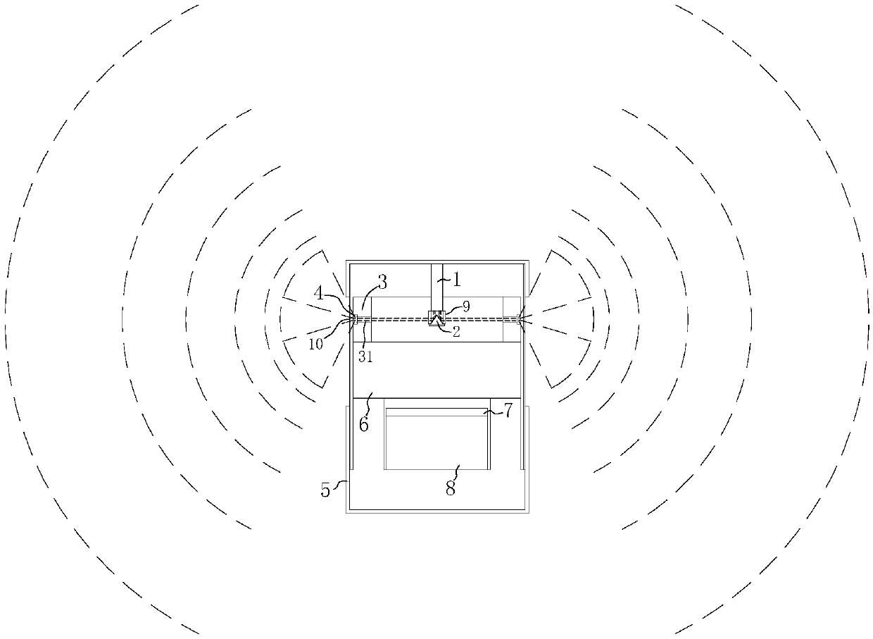
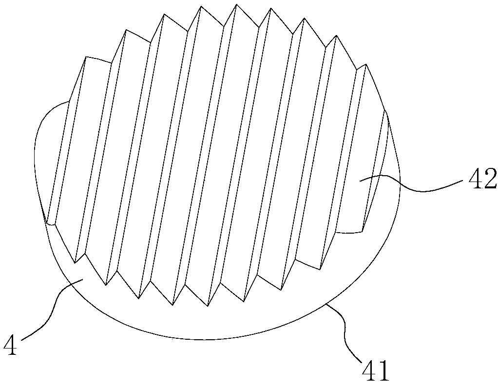
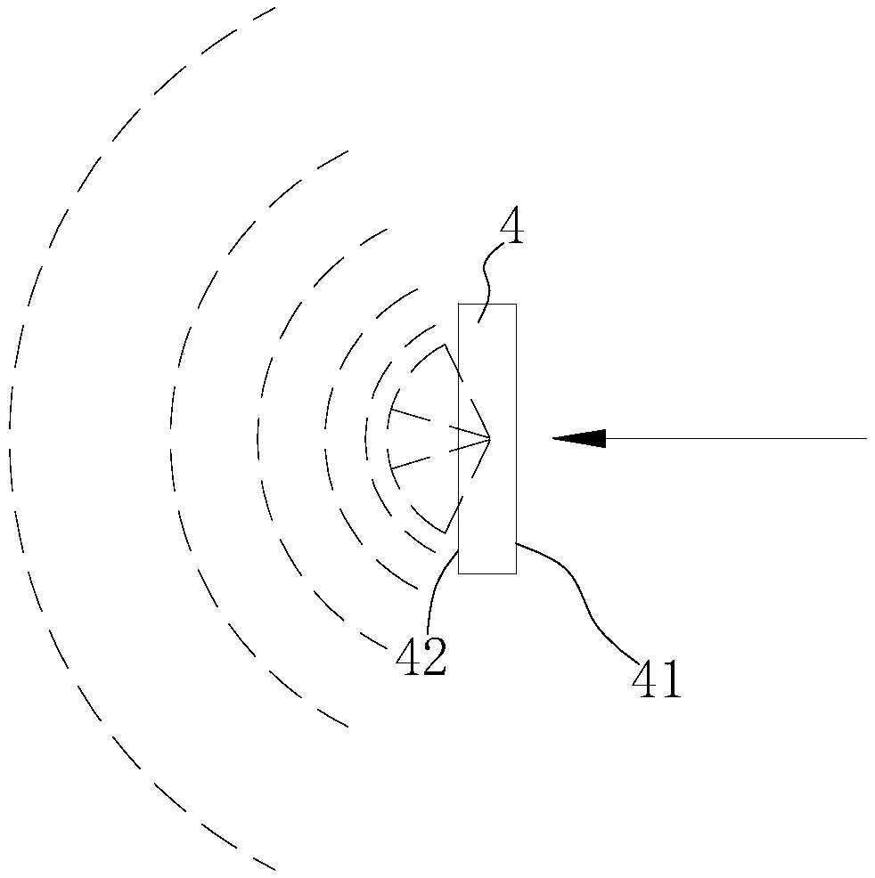
[0020] refer to Figure 1 to Figure 5 , the present invention is a kind of laser emission device, comprises laser emitter 1, and the emitting port of laser emitter 1 is provided with conical emitting mirror 2, also comprises the turntable 3 that is coaxially arranged with conical emitter mirror 2, and turntable 3 There are several lumens 31 arranged radially on the top, and the outside of the lumens 31 is provided with an optical lens 4 for forming a laser beam into a laser surface.

[0021] In this laser emitting device, the laser emitter 1 emits a laser beam, and the laser beam is reflected by the conical emitting mirror 2 to form multiple horizontal laser beams, wherein part of the laser beam passes through the lumen 31 on the turntable 3 and passes through the outside of the lumen 31 The optical lens 4 makes the laser beam form a laser surface. In this way, one laser emitter 1 can be used to emit multiple laser surfaces, and the overall structure is simple. Traditional me...


PUM


Abstract

The invention discloses a laser emitting device, which comprises a laser emitter, wherein the emitting port of the laser emitter is provided with a conical emitting mirror. The laser emitting device further comprises a rotating disc arranged in a mode of being coaxial with the conical emitting mirror, wherein the rotating disc is provided with a plurality of radially arranged tube cavities, and the outer side of each tube cavity is provided with an optical lens capable of turning a laser beam into a laser plane. According to the laser emitting device, the laser emitter emits a beam, the laserbeam is reflected by the conical emitting mirror and forms multiple parallel laser beams, part of the laser beams pass through the tube cavities on the rotating disc, and the laser beam is turned intoa laser plane through the optical lens outside each tube cavity. The laser emitter is fixed, and the rotating disc rotates, so that the laser plane is enabled to have a rotating effect. Therefore, multiple laser planes can be emitted by adopting one laser emitter. In addition, the laser emitting device is simple in overall structure and applied to the field of laser equipment.

Description

technical field [0001] The invention relates to the field of laser equipment, in particular to a laser emitting device. Background technique [0002] Existing widely used positioning technologies or positioning systems include Global Positioning System (GPS), ultrasonic positioning technology, infrared positioning technology, radio positioning technology, laser scanning triangulation positioning system, etc. Among them, the positioning accuracy of the laser scanning triangulation positioning system is relatively high. By setting the base station and the main station, the laser transmitter is set on the base station, the base station emits the laser to the main station, the base station collects the angle between the laser and the baseline, and through the angle and The baseline length determines the position of the master. In the existing laser scanning triangulation positioning systems, the transmitter emits a laser beam, and the target positioning data is refreshed every ...

Claims


Application Information

Patent Timeline
IPC IPC(8): G01S17/48G01S7/481
CPCG01S7/4814G01S17/48
Inventor 陈思烨
Owner 广州市慧建科技有限公司
Learn More