
Laser radar obstacle recognition method and device

An obstacle recognition and lidar technology, applied in the field of automatic control, can solve problems such as obstacle recognition errors

Active Publication Date: 2019-04-16
APOLLO INTELLIGENT DRIVING (BEIJING) TECHNOLOGY CO LTD
View PDF5 Cites 18 Cited by
  • Summary
  • Abstract
  • Description
  • Claims
  • Application Information

AI Technical Summary

Problems solved by technology

[0004] Various aspects of the present application provide a lidar obstacle recognition method and device to solve the problem of obstacle recognition errors caused by obstacles partially entering the lidar blind zone

Method used


Image

  • Laser radar obstacle recognition method and device
  • Laser radar obstacle recognition method and device
  • Laser radar obstacle recognition method and device

Examples


Embodiment Construction

[0039] In order to make the purposes, technical solutions and advantages of the embodiments of the present application clearer, the technical solutions in the embodiments of the present application will be clearly and completely described below in conjunction with the drawings in the embodiments of the present application. Obviously, the described embodiments It is a part of the embodiments of this application, not all of them. Based on the embodiments in this application, all other embodiments obtained by persons of ordinary skill in the art without creative efforts fall within the protection scope of this application.

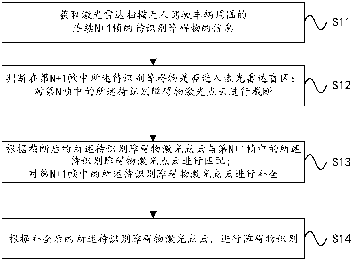
[0040] figure 1 A schematic diagram of a lidar obstacle recognition method provided by an embodiment of the present application, such as figure 1 shown, including the following steps:

[0041] Step S11, obtaining the information of obstacles to be identified in consecutive N+1 frames around the unmanned vehicle scanned by the lidar;

[0042] Step S12, acco...


PUM


Abstract

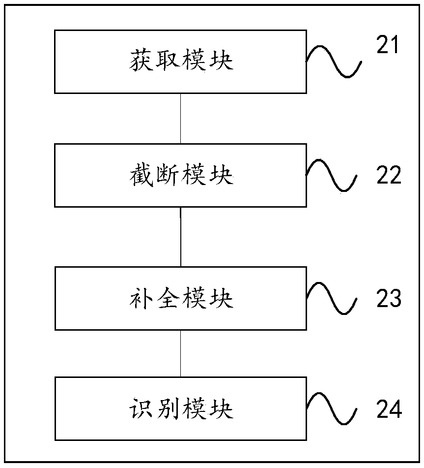
The invention provides a laser radar obstacle recognition method and device. The method comprises the following steps that information of to-be-recognized obstacles of continuous N+1 frames around anunmanned vehicle is obtained through laser radar scanning; whether the to-be-recognized obstacle in the (N+1)th frame enters a laser radar blind area or not is judged; an obstacle laser point cloud ofthe to-be-recognized obstacle in the Nth frame is cut off according to the length of the to-be-recognized obstacles entering the laser radar blind area; according to the cut-off laser point cloud ofthe to-be-recognized obstacle, the laser point cloud of the to-be-recognized obstacle in the (N+1)th frame is matched; completion is carried out on the laser point cloud of the to-be-recognized obstacle in the (N+1)th frame; and obstacle recognition is carried out according to the completed laser point cloud of the to-be-recognized obstacle. According to the method and device, a part of the obstacles entering the laser radar blind area can be recognized, so that the collision risk caused by error recognition of lengths and distances of the obstacles is avoided, and the driving safety of the unmanned vehicle is effectively improved.

Description

【Technical field】 [0001] The present application relates to the field of automatic control, in particular to a laser radar obstacle recognition method and device. 【Background technique】 [0002] In unmanned vehicles, multiple types of sensors are integrated: GPS-IMU (inertial measurement unit, Inertial Measurement Unit) integrated navigation module, cameras, lidar, millimeter wave radar and other sensors. [0003] During the driving process of unmanned vehicles, it mainly relies on lidar to detect obstacles, and lidar can realize accurate shape perception of obstacles. However, since the lidar is installed at the front center of the top of the unmanned vehicle, its vertical field of view ranges from plus or minus 15 degrees. Blocked by the body of the unmanned vehicle, there is a blind area of ​​vision, generally in the range of 6-7m. Therefore, the obstacle detection of existing unmanned vehicles can only detect obstacles that appear in the field of view of the lidar. As...

Claims


Application Information

Patent Timeline
IPC IPC(8): G01S17/93G01S7/48
CPCG01S7/4802G01S17/931
Inventor 朱晓星刘祥杨凡
Owner APOLLO INTELLIGENT DRIVING (BEIJING) TECHNOLOGY CO LTD
Learn More