Optical device coupling device and coupling method

A technology of coupling device and optical device, which is applied to the coupling of optical waveguides, optical components, light guides, etc., can solve the problems of low coupling and welding efficiency of optical devices and adapters.

Inactive Publication Date: 2019-04-16
GUANGXUN SCI & TECH WUHAN
View PDF9 Cites 8 Cited by
  • Summary
  • Abstract
  • Description
  • Claims
  • Application Information

AI Technical Summary

Problems solved by technology

[0002] In the field of design and manufacture of optical communication devices, the optical device needs to be coupled and welded with the adapter. During the welding operation, it is necessary to ensure that the optical device and the adapter are coaxial in the axial direction, and at the same time, the soft belt of the optical device needs to be powered. Usually The solution is to fix the optical device on the multi-dimensional fine-tuning frame, first adjust the multi-dimensional fine-tuning frame to position the optical device in the horizo...

Method used


Image

  • Optical device coupling device and coupling method
  • Optical device coupling device and coupling method
  • Optical device coupling device and coupling method

Examples


Embodiment 1

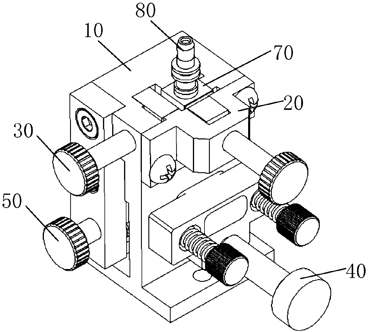
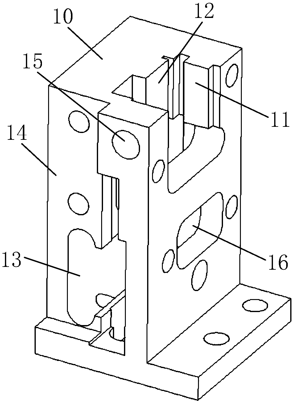
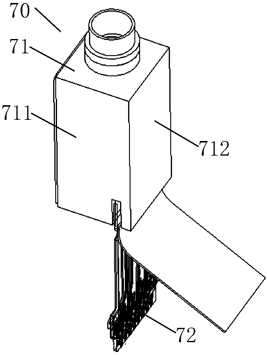
[0037] Embodiment 1 of the present invention provides an optical device coupling device, such as figure 1 As shown, it is an assembly diagram of an optical device coupling device provided by an embodiment of the present invention, including a coupling base 10, a top pressure component 20, a side pressure component 30, a soft belt pressure component 40, a PCB adjustment component 50, an optical device 70 is disposed on the coupling base 10 , and the adapter 80 is installed on the optical device 70 to facilitate welding with the optical device 70 . The top pressure assembly 20 and the side pressure assembly 30 are used to position the main body of the optical device 70; the PCB adjustment assembly 50 and the soft belt pressurization assembly 40 are used to connect the flexible belt of the optical device 70 to the power PCB. connect. Among them, the pressing assembly 20 and the flexible belt pressing assembly 40 are arranged on the front of the coupling base 10, and the pressing...

Embodiment 2

[0045] Embodiment 2 of the present invention provides an optical device coupling method, using the structure of the optical device coupling device described in Embodiment 1, such as Figure 9 as shown, Figure 9 It is a flow chart of an optical device coupling method provided by an embodiment of the present invention. The following optical device coupling methods are combined Figure 1 to Figure 8 To illustrate, optical device coupling methods include:

[0046] Step 100: Adjust the top pressure component, the side pressure component and the soft belt pressure component, and place the optical device in the coupling base;

[0047] Adjust the pressing assembly 20, the side pressing assembly 30 and the soft belt pressing assembly 40, that is, unscrew the pressing rod 22 of the pressing assembly 20, and the pressing rod 22 drives the pressing slide block 23 to retreat; the side pressing assembly 30 The side pressure pull rod 31 is unscrewed, and the side pressure pull rod 31 driv...


PUM


Abstract

The invention discloses an optical device coupling device and a coupling method. The coupling device comprises a coupling base, a top pressing assembly, a side pressing assembly, a soft belt pressurization assembly, a PCB adjusting assembly and an electrifying PCB, wherein the top pressing assembly, the side pressing assembly, the soft belt pressurizing assembly and the PCB adjusting assembly areconnected with the coupling base, the electrifying PCB is arranged on the PCB adjusting assembly, the top pressing assembly and the side pressing assembly are used for positioning the main body part of the optical device, and the PCB adjusting assembly and the soft belt pressurizing assembly are used for connecting the soft belt of the optical device with the electrifying PCB. When the optical device and an adapter are coupled for welding, a multi-dimensional fine adjustment frame is not needed, the top pressing assembly and the side pressing assembly of the optical device coupling device areadjusted to position the optical device, meanwhile, the relative position relation between the optical device and the adapter is ensured, the soft belt pressurizing assembly and the PCB adjusting assembly are adjusted to enable the soft belt of the optical device and the electrifying PCB to be electrified smoothly, so that the coupling efficiency and the coupling quality of the optical device andthe adapter are improved.

Description

【Technical field】 [0001] The invention relates to the field of manufacturing optical communication devices, in particular to an optical device coupling device and a coupling method. 【Background technique】 [0002] In the field of design and manufacture of optical communication devices, the optical device needs to be coupled and welded with the adapter. During the welding operation, it is necessary to ensure that the optical device and the adapter are coaxial in the axial direction, and at the same time, the soft belt of the optical device needs to be powered. Usually The solution is to fix the optical device on the multi-dimensional fine-tuning frame, first adjust the multi-dimensional fine-tuning frame to position the optical device in the horizontal direction, and then adjust the multi-dimensional fine-tuning frame to make the optical device vertical to the adapter on the welding fixture; before coupling and welding the optical device and the adapter Firstly, solder the fl...

Claims


Application Information

Patent Timeline
IPC IPC(8): G02B6/42
CPCG02B6/4219G02B6/4236G02B6/428
Inventor 杨宇翔梅晓鹤余斯佳全本庆
Owner GUANGXUN SCI & TECH WUHAN
Why Eureka
Try Eureka