A terminal heat dissipation structure and a heat dissipation control method

A technology of heat dissipation structure and control method, which is applied to instruments, electrical digital data processing, digital data processing components, etc., can solve the problems of easy entry of dust in terminals, affecting user experience, and damaging the service life of mobile terminals.

Inactive Publication Date: 2019-04-16
NUBIA TECHNOLOGY CO LTD
View PDF6 Cites 1 Cited by
  • Summary
  • Abstract
  • Description
  • Claims
  • Application Information

AI Technical Summary

Problems solved by technology

For this type of mobile terminal, the existence of the air outlet will lead to the phenomenon that the terminal is easy to get dust, which will damage the service life of the mobile terminal and affect the user experience.

Method used


Image

  • A terminal heat dissipation structure and a heat dissipation control method
  • A terminal heat dissipation structure and a heat dissipation control method
  • A terminal heat dissipation structure and a heat dissipation control method

Examples


no. 1 example

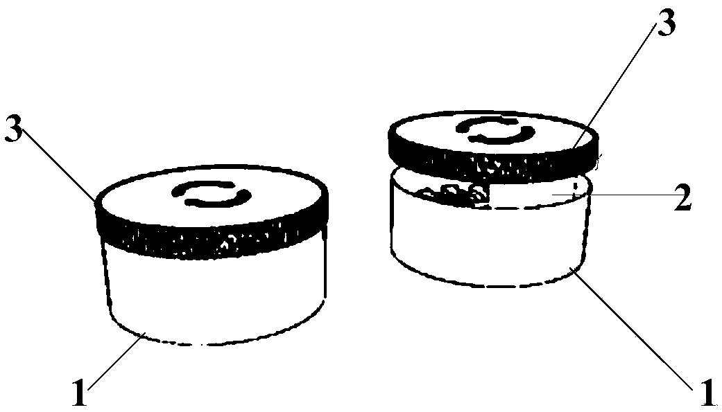
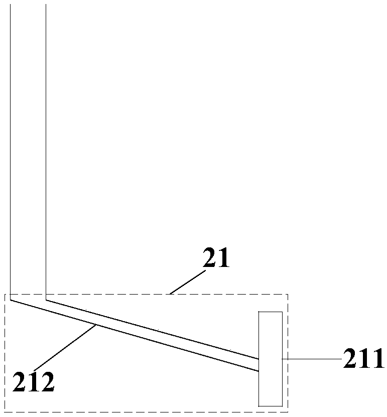
[0059] Aiming at the technical problems that current mobile terminals adopt air cooling technology for heat dissipation, the terminal is prone to ash ingress, which will damage the service life of the mobile terminal and affect the user experience. This embodiment provides a terminal heat dissipation structure. The heat dissipation structure It can be applied to mobile terminals that adopt air-cooling technology for heat dissipation. see figure 2 As shown, the heat dissipation structure includes a heat dissipation wall 1 enclosing a heat dissipation channel, a connecting part 2 arranged in the heat dissipation channel that can be stretched up and down, and a dustproof cover 3 connected to one end of the connecting part 2 .

[0060] In this embodiment, in one state, the dust cover 3 can abut against the heat dissipation wall 1 so as to close the heat dissipation channel. At this time, there is no heat dissipation vent or the heat dissipation vent is closed, which is applicabl...

no. 2 example

[0081] This embodiment proposes a heat dissipation control method on the basis of the terminal heat dissipation structure of the motor in the first embodiment above. see Figure 6 shown, including:

[0082] S601: Detect the current state of the terminal;

[0083] In this embodiment, the terminal can monitor the state of the terminal itself in real time through a detection program.

[0084]S602: When it is detected that the current state of the terminal satisfies the preset heat dissipation condition, turn on the air cooling function and control the rotation of the motor to form a heat dissipation port;

[0085] In this embodiment, the preset heat dissipation condition may include: the terminal starts an application in a preset set, and / or, the temperature of the terminal reaches a preset temperature threshold.

[0086] In this embodiment, the applications in the preset collection may be applications with high energy consumption in the terminal, such as applications such as ...

no. 3 example

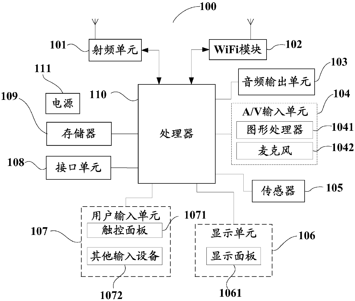
[0095] This embodiment provides a terminal, see Figure 7 As shown, it includes a processor 701 , a memory 702 and a communication bus 703 . in:

[0096] The communication bus 703 is used to realize connection and communication between the processor 701 and the memory 702 .

[0097] The processor 701 is configured to execute one or more programs stored in the memory 702, so as to implement each step of the heat dissipation control method in the second embodiment above.

[0098] This embodiment provides a computer-readable storage medium, such as a floppy disk, a CD, a hard disk, a flash memory, a USB flash drive, a CF card, an SD card, an MMC card, etc., in which a computer-readable storage medium is stored to implement the above steps. Or a plurality of programs, the one or more programs can be executed by one or more processors, so as to implement the steps of the heat dissipation control method in the second embodiment above. I won't repeat them here.


PUM


Abstract

The invention discloses a terminal heat dissipation structure and a heat dissipation control method, and the terminal heat dissipation structure is designed and comprises a heat dissipation wall whichforms a heat dissipation channel in a surrounding manner, a connecting part which is arranged in the heat dissipation channel and can extend and retract up and down, and a dustproof cover connected with one end of the connecting part. Wherein the dustproof cover abuts against the heat dissipation wall, and when the connecting part moves upwards, the dustproof cover is separated from the heat dissipation wall to form a heat dissipation opening. Therefore, the design of the dustproof cover is adopted; The dustproof cover can be moved upwards to form the heat dissipation opening for heat dissipation only when air cooling heat dissipation is needed, and the dustproof cover can abut against the heat dissipation wall when air cooling heat dissipation is not needed, so that the problem that dustenters the terminal due to the existence of the heat dissipation opening is greatly reduced, the service life of the terminal is guaranteed, and the user experience is improved.

Description

technical field [0001] The present invention relates to the technical field of terminals, and more specifically, to a terminal heat dissipation structure and a heat dissipation control method. Background technique [0002] With the continuous development of terminal technology, there are more and more categories of terminals. At present, mobile terminals (such as Red Magic mobile phones, etc.) that adopt air-cooling technology for heat dissipation have appeared. For this type of mobile terminal, due to the existence of the air outlet, the terminal is prone to dust, which will damage the service life of the mobile terminal and affect the user experience. Contents of the invention [0003] The technical problem to be solved by the present invention is: in the current mobile terminals that adopt air cooling technology for heat dissipation, the terminal is prone to ash ingress, which damages the service life of the mobile terminal and affects the user experience. To solve th...

Claims


Application Information

Patent Timeline
Patent Type & Authority Applications(China)
IPC IPC(8): G06F1/20
CPCG06F1/203
Inventor 黄飞力
Owner NUBIA TECHNOLOGY CO LTD
Why Eureka
Try Eureka