Electric connector

A technology of electrical connectors and wires, which is applied in the direction of connection, parts and circuits of connection devices, to achieve the effect of stable maintenance

Active Publication Date: 2019-04-16
SMK CO LTD
View PDF5 Cites 0 Cited by
  • Summary
  • Abstract
  • Description
  • Claims
  • Application Information

AI Technical Summary

Problems solved by technology

[0008] The object of the present invention is to provide an electric connector that does not cause damage to the electric wires when stretching the wound electric wires, and can hold the electric wires stably when the electric wires are connected.

Method used


Image

  • Electric connector
  • Electric connector
  • Electric connector

Examples


Embodiment Construction

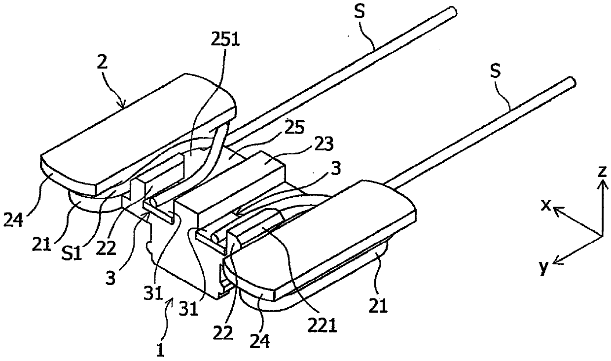
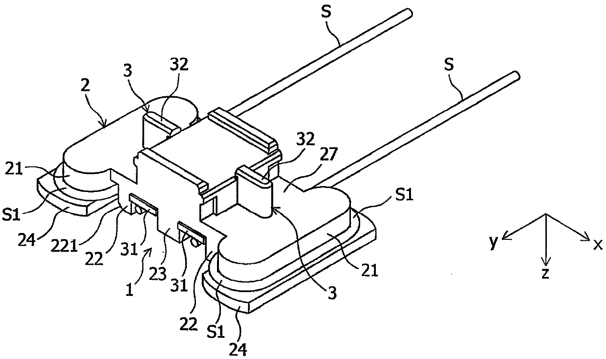
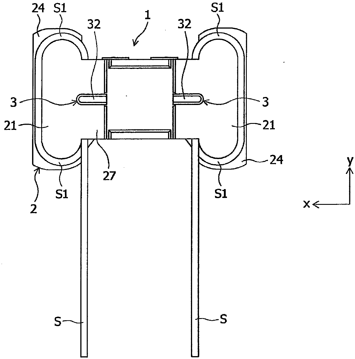
[0059] Hereinafter, the electrical connector according to the embodiment of the present invention will be described in detail with appropriate reference to the drawings. In the figure, the x-axis, y-axis and z-axis form a three-axis orthogonal coordinate system, the positive direction of the y-axis is taken as the front direction, the negative direction of the y-axis is taken as the rear direction, and the x-axis direction is taken as the left-right direction, The positive direction of the z-axis is defined as an upward direction, and the negative direction of the z-axis is defined as a downward direction.

[0060] (first embodiment)

[0061]

[0062] Below, refer to Figure 1 to Figure 7 , the configuration of the electrical connector 1 according to the first embodiment of the present invention will be described in detail. in addition, Figure 1 ~ Figure 4 , a state in which the electric wire S is connected to the electrical connector 1 of this embodiment is shown.

[0...


PUM


Abstract

When a wound wire is stretched, there is no damage to the wire, and the wire can be stably held when being connected. An electric connector (1) connected to an electric wire (S) is provided with an insulating housing (2); And a joint (3) which is provided with a terminal part (31) that is exposed from the housing (2) and is connected to the electric wire (S), is held by the housing (2), and has electrical conductivity. The housing (2) is provided with a winding part (21) around which the electric wire (S) is wound, the surface of the winding part (21), which is in contact with the folded-backpart (S1) of the electric wire (S), being a curved surface; and a left-right restricting part (22) and a left-right restricting part (23) that are provided in parallel to the left and right of the terminal part (31) and restrict the movement of the electric wire (S) in the left-right direction.

Description

technical field [0001] The present invention relates to an electrical connector connected to electric wires such as enameled wires. Background technique [0002] From the prior art, the wiring configuration of electric wires with soldered connection of electric wires is well known for electrical terminals. The junction structure of the electric wire is hard and brittle because the boundary between the electric wire embedded in the solder and the electric wire positioned outside the solder is hard and brittle, so if a bending or stretching force is applied to this part, the electric wire will break easily. Wire. [0003] On the other hand, Patent Document 1 discloses an electric wire connection structure in which electric wires are wound and connected to electrical terminals. Specifically, in the wiring structure of the electric wire of Patent Document 1, the electric wire of the covered wire will be wound once at the vertical erected portion of the electrical terminal, and...

Claims


Application Information

Patent Timeline
Patent Type & Authority Applications(China)
IPC IPC(8): H01R13/502H01R13/72
CPCH01R13/502H01R13/72
Inventor 托利斯·安里克浅井清鸨田润一
Owner SMK CO LTD
Why Eureka
Try Eureka