Power lift

A technology of power machines and lifting cylinders, which is applied in the directions of lifting devices, lifting frames, mechanically driven excavators/dredgers, etc., can solve problems such as being not optimal and expensive.

Active Publication Date: 2019-04-16
CLARK EQUIP CO INC
View PDF3 Cites 0 Cited by
  • Summary
  • Abstract
  • Description
  • Claims
  • Application Information

AI Technical Summary

Problems solved by technology

Both options are expensive and may not be preferred for various reasons

Method used


Image

  • Power lift
  • Power lift
  • Power lift

Examples


Embodiment Construction

[0020] The concepts disclosed in this discussion are described and illustrated with reference to exemplary embodiments. However, these concepts are not limited in their application to the structural details and the arrangement of components in the exemplary embodiment, and can be practiced or carried out in various other ways. The terms used in this document are used for the purpose of description and should not be regarded as limiting. Words such as "comprises," "comprising," and "having" and variations thereof as used herein are meant to encompass the items listed thereafter, equivalents thereof, and additional items.

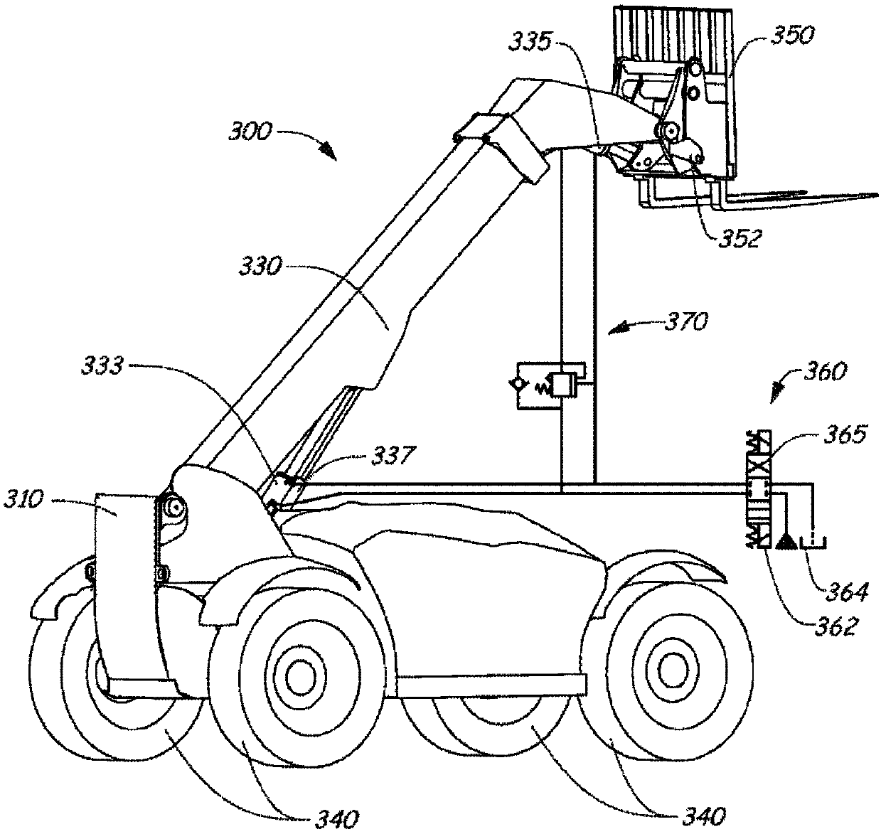
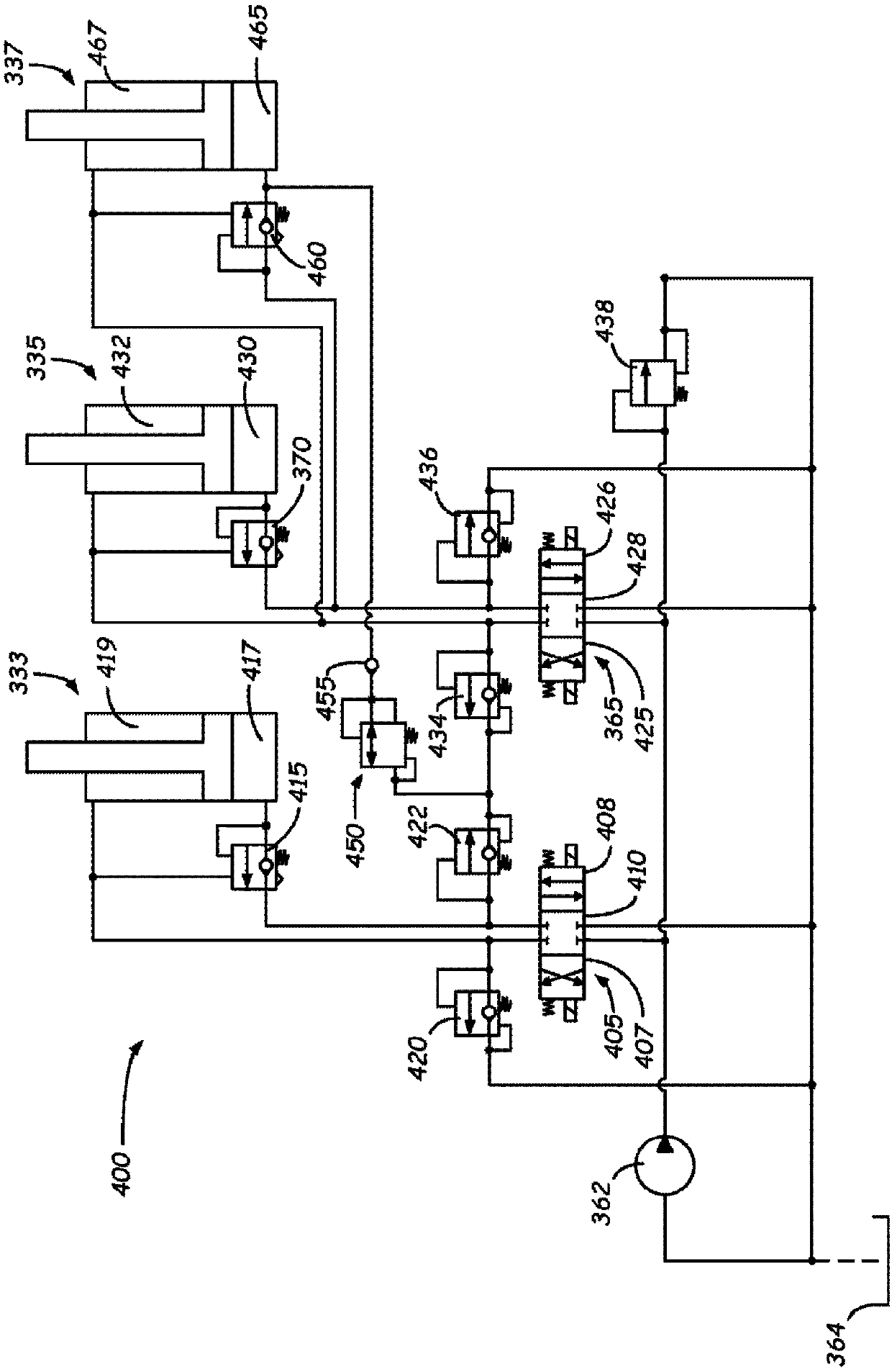
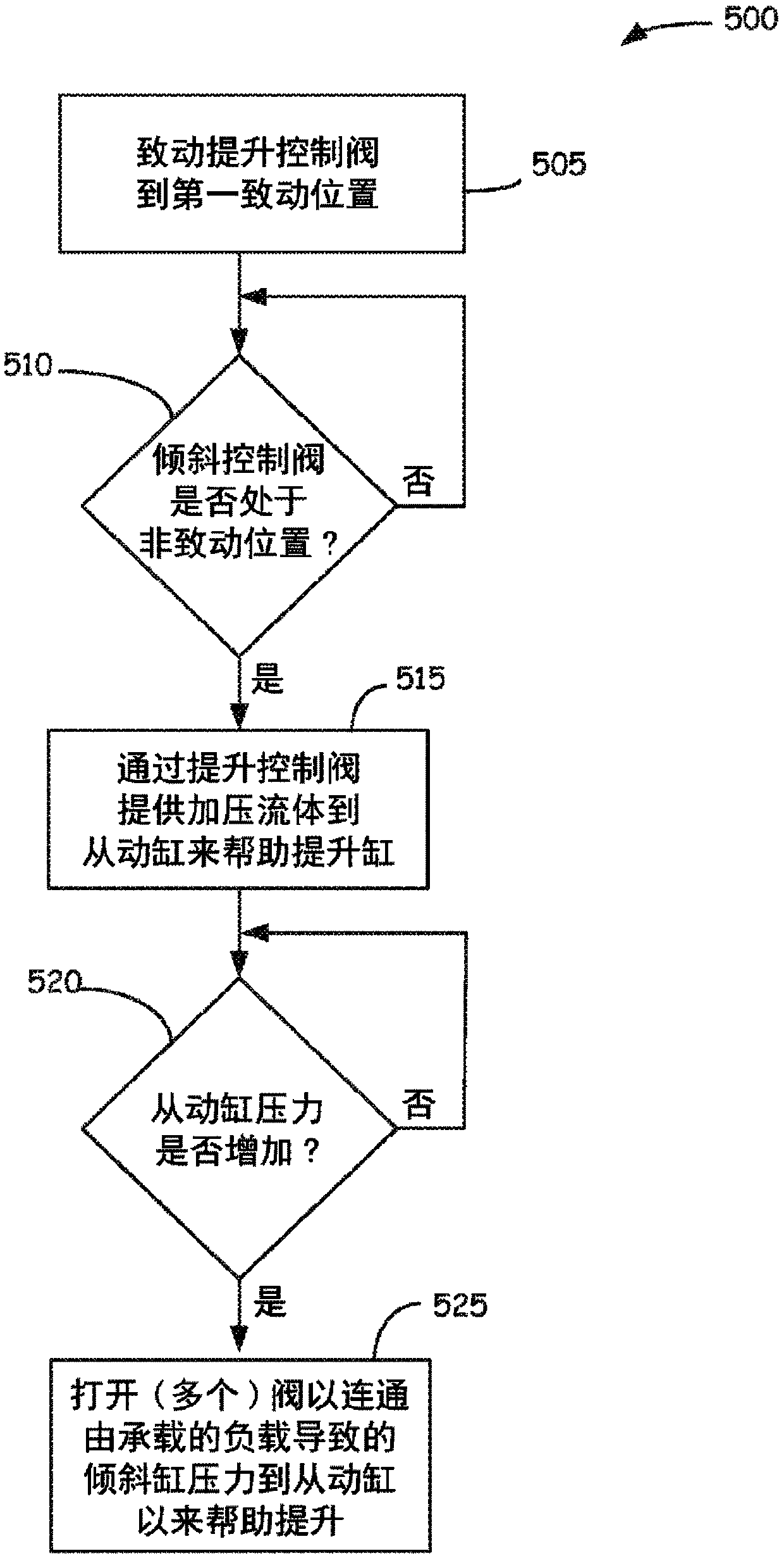
[0021]The disclosed embodiments relate to a power machine and a control system or hydraulic circuit for use on the power machine that includes a lift cylinder, a tilt cylinder, and a slave cylinder mechanically connected in parallel with the lift cylinder to raise a boom. With the lift control valve controlled to cause the lift cylinder to extend to raise th...


PUM


Abstract

Power machines (300) and control systems (360, 400) used thereon include a lift cylinder (333), a tilt cylinder (335), and a slave cylinder (337) mechanically connected to assist the lift cylinder with raising a boom (330). With a lift control valve (405) controlled to cause extension of the lift cylinder to raise the boom, pressure from a hydraulic source (362) is provided to the slave cylinder to aid in raising the boom. Resulting increased pressure on a side of the slave cylinder opens load holding valves (370, 460), allowing hydraulic pressure from the tilt cylinder to be communicated to the slave cylinder such that tilt cylinder pressure due to a heavy load on an implement aids in raising the boom.

Description

technical field [0001] This disclosure relates to powered machines. More specifically, the present disclosure relates to powered machines having lift cylinders and self-leveling tilt cylinders. Background technique [0002] For the purposes of this disclosure, a powered machine includes any type of machine that generates power for the performance of a particular task or tasks. One type of powered machine is a work vehicle. Work vehicles, such as telehandlers, are typically self-propelled vehicles having work equipment, such as a lift arm or boom, that can be maneuvered to perform work functions (although some work vehicles may have other work equipment as well). In addition to telescopic boom loaders, work vehicles include loaders, excavators, utility vehicles, tractors, and trenchers, just to name a few. [0003] Telehandlers are often equipped with self-leveling hydraulic systems to help keep the fork tilt constant during the lifting movement of the boom. In some desig...

Claims


Application Information

Patent Timeline
Patent Type & Authority Applications(China)
IPC IPC(8): E02F3/43E02F9/20B66F7/22B66F9/04E21B7/00
CPCE02F3/432E02F3/433E02F3/436E02F9/2029E02F9/2041F15B2211/50554F15B2211/30515F15B2211/30585F15B2211/30595F15B2211/3111F15B2211/50518F15B2211/50545F15B2211/50581F15B2211/5153F15B2211/5156F15B2211/7128F15B2211/7142B66F9/0655B66F9/22B66F7/22E21B7/00E02F9/2225
Inventor 尼古拉斯·盖尔斯
Owner CLARK EQUIP CO INC
Why Eureka
Try Eureka