Coagulation detection chip and coagulation detection method

A detection chip, blood coagulation technology, applied in the field of blood coagulation detection

Inactive Publication Date: 2019-04-19
邓治杨 +1
View PDF7 Cites 0 Cited by
  • Summary
  • Abstract
  • Description
  • Claims
  • Application Information

AI Technical Summary

Problems solved by technology

However, this method requires the assistance of a microscope, and ABO blood group detection reagents are the basic requirements

Method used


Image

  • Coagulation detection chip and coagulation detection method
  • Coagulation detection chip and coagulation detection method
  • Coagulation detection chip and coagulation detection method

Examples


Embodiment 1

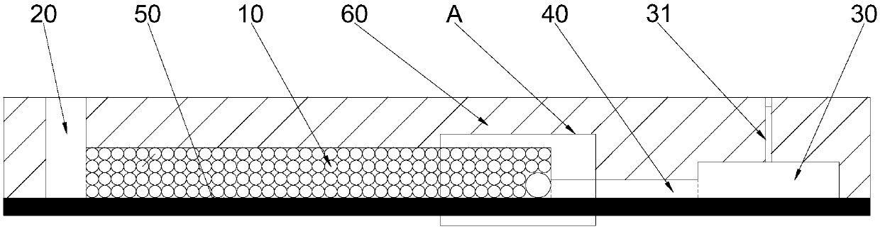
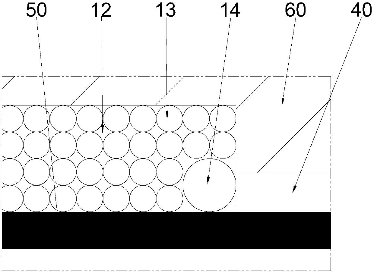
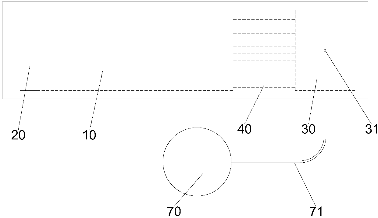
[0040] Such as figure 1 Shown is a schematic structural diagram of Embodiment 1 of the coagulation detection chip of the present invention. The blood coagulation detection chip of this embodiment includes a microchannel 10, the microchannel 10 includes a cavity 11 for accommodating red blood cells, the cavities 11 are distributed in a spatial array, and two adjacent cavities 11 are provided for red blood cells. Pass through the communication channel 12 that also blocks the flow of red blood cells. One end of the microchannel 10 is provided with a first blood sampling chamber 20, and the other end is provided with a collection chamber 30 for collecting plasma. The collection chamber 30 of this embodiment is provided with an air outlet 31; the blood coagulation detection chip of this embodiment also includes The second blood sampling cavity 70 is communicated with the second blood sampling cavity 70 and the collection cavity 30 by a capillary 71. A separation channel 40 for circ...

Embodiment 2

[0049] Such as Picture 11 Shown is a schematic structural diagram of Embodiment 2 of the coagulation detection chip of the present invention. The blood coagulation detection chip of this embodiment includes a microchannel 10, the microchannel 10 includes a cavity 11 for accommodating red blood cells, the cavities 11 are distributed in a spatial array, and two adjacent cavities 11 are provided for red blood cells. Pass through the communication channel 12 that also blocks the flow of red blood cells. One end of the microchannel 10 is provided with a first blood sampling chamber 20, and the other end is provided with a collection chamber 30 for collecting plasma. The collection chamber 30 in this embodiment is provided with an air outlet 31. The blood coagulation detection chip of this embodiment further includes a second blood sample injection cavity 70, and the second blood sample injection cavity 70 is communicated with the collection cavity 30 by a capillary 71. A separatio...


PUM


Abstract

The invention discloses a coagulation detection chip which comprises a micro-channel, wherein the micro-channel comprises accommodating cavities for accommodating red blood cells, accommodating cavities are distributed in a spatial array, and a communication channel which can be used for red blood cells to pass through and simultaneously plays a role in blocking the flow of the red blood cells isarranged between two adjacent containing cavities; one end of the micro-channel is provided with a first blood sample introduction cavity, and the other end of the micro-channel is provided with a collection cavity for collecting plasma; and a second blood sampling cavity communicated with the collection cavity is arranged on the collection cavity. The invention also discloses a blood coagulationdetection method which is characterized by comprising the following steps of: 1) dripping a first blood sample into the first blood sample introduction cavity, separating red blood cells and plasma ofthe first blood sample by utilizing a microchannel, and stacking the separated plasma in the collection cavity; 2) dripping a second blood sample into the second blood sample introduction cavity whenthe blood plasma fills the collection cavity, and entering the second blood sample into the collection cavity; 3) detecting a coagulation reaction between the first blood sample and the second bloodsample.

Description

Technical field [0001] The invention belongs to the technical field of coagulation detection, and specifically is a coagulation detection chip and a coagulation detection method. Background technique [0002] Clinically, patients in need of blood transfusion will perform coagulation tests on their blood and the donor’s blood before blood transfusion treatment to test whether the two are coagulated. Only non-coagulated blood can be delivered to the patient. The current coagulation detection method mainly measures the patient’s blood type first. The red blood cell surface antigens in blood of different blood types are different, and the human body will only produce different antibodies. For example, the red blood cell surface antigen in type A blood is agglutinogen A. Its plasma contains anti-B lectin, the surface antigen of red blood cells in type B blood is agglutinogen B, and its plasma contains anti-A lectin, and the surface of type AB red blood cells has two types of agglutino...

Claims


Application Information

Patent Timeline
Patent Type & Authority Applications(China)
IPC IPC(8): B01L3/00G01N33/80
CPCB01L3/5027B01L3/502753B01L2200/10G01N33/80
Inventor 邓治杨杨雁婷
Owner 邓治杨
Why Eureka
Try Eureka