
Cold repair welding machine electrode tip

An electromechanical and cold compensation technology, applied in the direction of electrode features, roller electrodes, etc., can solve the problems of difficult to guarantee welding position, hot electrode hair, low welding efficiency, etc., to ensure the welding effect, large pressing force, and prevent burns.

Inactive Publication Date: 2019-04-19
GREAT WALL MOTOR CO LTD
View PDF11 Cites 1 Cited by
  • Summary
  • Abstract
  • Description
  • Claims
  • Application Information

AI Technical Summary

Problems solved by technology

[0005] 1. The plug and connector are made of brass. Due to the large current during welding, the entire electrode head will often heat up severely. In order to prevent burns, the electrode head needs to be cooled after welding for a certain period of time, so that the electrode head cannot be used for a long time. work, but will affect the welding efficiency
[0006] 2. The connector and the plug are connected together by plugging, and the connector needs to be rotated relative to the plug, so the plugging part is easily damaged during use, which will affect the welding operation
[0007] 3. The existing electrode head needs to be held in both hands during use. One hand positions the electrode head, and the other hand rotates the joint for welding. Since the electrode is relatively thin, the electrode must be pressed down hard when the electrode is rolling. Therefore, the whole welding operation process will cause great damage to the wrist of the welder, and the wrist is easily fatigued, so it cannot work for a long time
[0008] 4. The existing electrode head is pressed down with one hand during welding, which easily leads to difficulty in positioning the electrode head, and it is difficult to ensure the welding position, which affects the welding effect
Moreover, the existing electrode head will also make the welding efficiency lower because the electrode is thinner and the welding area is small.

Method used


Image

  • Cold repair welding machine electrode tip
  • Cold repair welding machine electrode tip
  • Cold repair welding machine electrode tip

Examples


Embodiment Construction

[0036] It should be noted that, in the case of no conflict, the embodiments of the present invention and the features in the embodiments can be combined with each other.

[0037] The present invention will be described in detail below with reference to the accompanying drawings and examples.

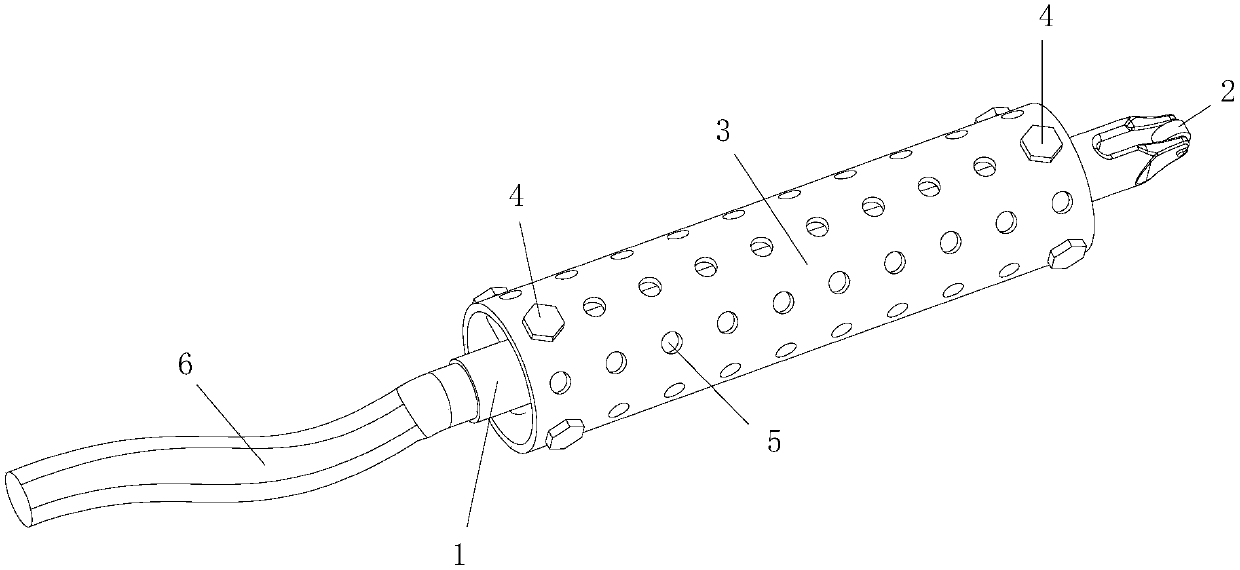
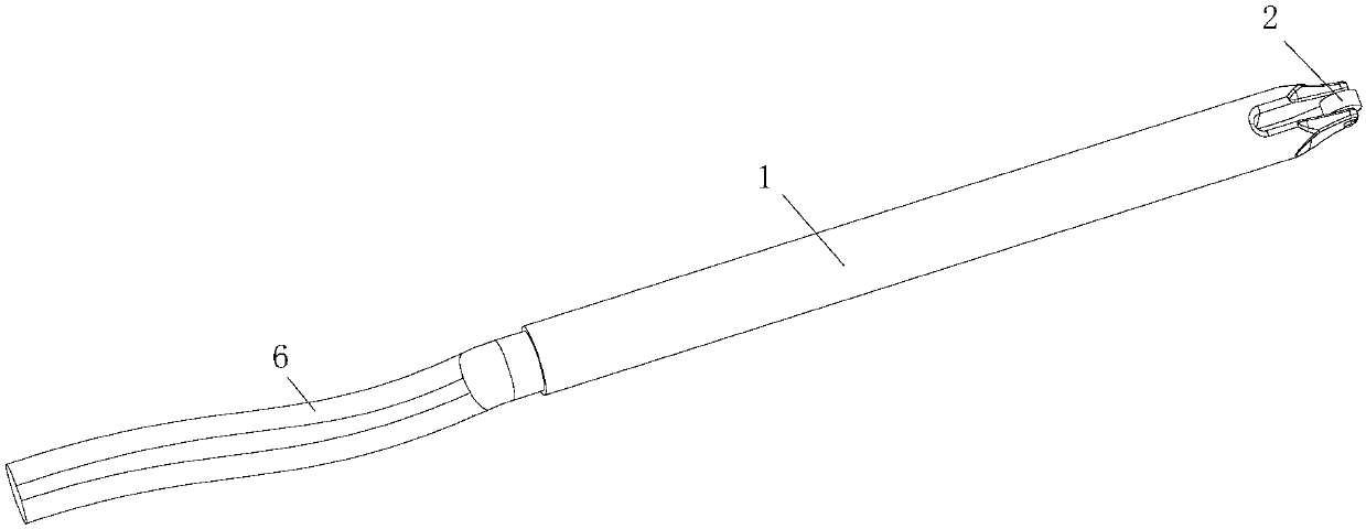
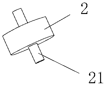
[0038] This embodiment relates to an electrode head of a cold repair welding machine, and its overall structure includes a plug and a hand-held part corresponding to the outer peripheral side of the plug, wherein one end of the plug is a cable connection end, relative to the cable connection end, The other end of the plug is provided with an electrode that can roll and press against the workpiece to be welded. The handle has an extension length along the axial direction of the plug, and the plug is fixed in the handle by a positioning component and is spaced from the handle. The end of the plug with the electrodes is also located outside the handle.

[0039] The electrode tip of the col...


PUM


Abstract

The invention provides a cold repair welding machine electrode tip. The cold repair welding machine electrode tip comprises a plug and a handheld part; one end of the plug is a cable connecting end, opposite to the cable connecting end, the other end of the plug is provided with an electrode which is capable of rolling against a to-be-welded workpiece; and the handheld part is arranged corresponding to the outer peripheral side of the plug and has an extending length along the axial direction of the plug, the plug is fixed in the handheld part through a positioning assembly and is spaced apartfrom the handheld part, and one end, with the electrode, of the plug is located outside the handheld part. The cold repair welding machine electrode tip can overcome defects existing in an existing cold repair welding machine electrode tip, so that the electrode tip with a good use effect can be provided.

Description

technical field [0001] The invention relates to the technical field of welding equipment, in particular to an electrode head of a cold repair welding machine. Background technique [0002] The cold repair welding machine is also called the mold cold repair machine. It is mainly used for repairing the mold. It presses the silicon steel sheet on the mold surface when it is in use. Using the principle of spot welding, the pulse current generated by the welding machine is partially welded by the electrode head. Melting to realize the welding of the silicon steel sheet on the mold surface. [0003] At present, the electrode heads used in cold repair welding machines are generally composed of cables, plugs, connectors, electrode caps and electrodes. It can rotate relative to the plug, and the electrode cap fixes the electrode on the joint. When in use, by rotating the joint, the electrode rolls on the workpiece to complete welding. [0004] Although the existing cold repair weld...

Claims


Application Information

Patent Timeline
Patent Type & Authority Applications(China)
IPC IPC(8): B23K11/30
CPCB23K11/3045
Inventor 孙继斌赵文强李松赵栋威曹少帅岳金龙李雷雷胡军涛
Owner GREAT WALL MOTOR CO LTD
Learn More