High-pressure integrated pump

A technology of high-pressure integration and pump casing, which is applied in the direction of pumps, pump components, variable displacement pump components, etc., to achieve the effect of balancing oil pressure and pressure equalization

Inactive Publication Date: 2019-04-19
FUJIAN JIANGXIA UNIV
View PDF6 Cites 0 Cited by
  • Summary
  • Abstract
  • Description
  • Claims
  • Application Information

AI Technical Summary

Problems solved by technology

The performance of the original hydraulic components cannot meet the requirements of the technical improvement of the main engine, and it is urgent to develop hydraulic components with high output pressure, high reliability, long service life, low noise and environmental protection

Method used


Image

  • High-pressure integrated pump
  • High-pressure integrated pump
  • High-pressure integrated pump

Examples


specific Embodiment approach

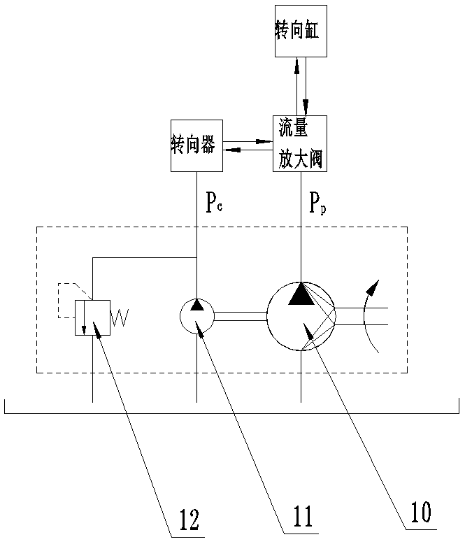
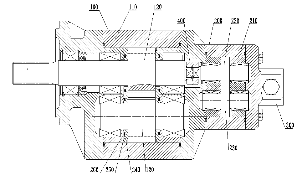
[0049] Specific implementation method: when working, the oil in the external oil tank flows into the low-pressure area of ​​the first pump casing through the oil inlet of the steering pump, and then flows into the low-pressure area of ​​the pilot pump through channel A. When the first driving gear rotates, it will simultaneously Drive the first driven gear and the second driving gear to rotate, and the rotation of the second driving gear will drive the rotation of the second driven gear. During the rotation process of the first driving gear and the first driven gear, the low pressure area of ​​the steering pump will be The oil is transported to the high-pressure area and flows out from the first oil outlet. During the rotation of the second driving gear and the second driven gear, the oil in the low-pressure area of ​​the pilot pump will be transported to the high-pressure area and flow out from the oil passage B. It flows into the relief valve, and then flows out from the seco...


PUM


Abstract

The invention relates to a high-pressure integrated pump. The high-pressure integrated pump comprises a steering pump, a pilot pump is arranged on the steering pump, and an overflow valve is arrangedon the pilot pump; the steering pump comprises a first pump shell, the first pump shell is provided with an oil inlet and a first oil outlet, a first drive gear is arranged in the first pump shell, and a first driven gear which meshes with the first drive gear and is used for delivering hydraulic oil together with the first drive gear is arranged radially beside the first drive gear; and the pilotpump comprises a second pump shell, a second drive gear which achieves coaxial transmission with the first drive gear is arranged in the second pump shell, a second driven gear which meshes with thesecond drive gear and is used for delivering the hydraulic oil together with the second drive gear is arranged radially beside the second drive gear, and a coupler is arranged between the first drivegear and the second drive gear. According to the high-pressure integrated pump, the pilot pump and the steering pump are integrated, the overflow valve is arranged to depressurize the high pressure side of the pilot valve, and therefore the pilot valve can not be overloaded.

Description

technical field [0001] The invention relates to a high-pressure integrated pump. Background technique [0002] Due to the advantages of small operating force and high efficiency, large-scale construction machinery generally adopts a two-stage hydraulic method of full hydraulic steering gear and flow amplification valve to realize steering movement. Such as figure 1 , is a schematic diagram of the oil supply for the pilot pump of a steering system of a large-scale engineering machinery. In the figure, 10 is the steering pump A, 11 is the pilot pump A, and 12 is the relief valve A. Steering pump A10 and pilot pump A11 are directly driven by the engine. Pilot pump A11 and overflow valve A12 form a constant pressure circuit to provide pressure and flow for the steering gear. The steering gear can drive the main valve of the flow amplifying valve. By switching the main valve, The on-off action controls the movement of the steering cylinder to achieve steering. [0003] With th...

Claims


Application Information

Patent Timeline
Patent Type & Authority Applications(China)
IPC IPC(8): F02B63/06F04B17/05F04B53/10F04B53/00
CPCF02B63/06F04B17/05F04B53/00F04B53/10
Inventor 郭善新
Owner FUJIAN JIANGXIA UNIV
Why Eureka
Try Eureka