Method for installing stator blade fixing cover and device using the same

A technology for installing a stator and a fixed cover, which is applied to the supporting elements, stators, and engine elements of the blades, etc., can solve the problems of high labor consumption, small tolerances of holes and rivets, and damage of fixed rivets and fixed blades, and achieves high accuracy and avoidance. deformation effect

Inactive Publication Date: 2015-11-25
弗拉斯季米尔·塞德拉切克
View PDF7 Cites 0 Cited by
  • Summary
  • Abstract
  • Description
  • Claims
  • Application Information

AI Technical Summary

Problems solved by technology

However, the hole and rivet tolerances were so tight that some rivets had to be pressed into the holes with such force that both the set rivet and the actual set vane were damaged
When all the covers are fastened to the ends of the fixed blades by means of raised rivets, the required artificial factors and external forces have the following consequences: uncontrollable artificial character in terms of their high labor consumption, strong shocks that negatively affect human organs and Mainly due to the inability to apply the proper force on the rivet, causing the overload of rivets that need to be driven down to the same height and the height of the rivet head is different

Method used


Image

  • Method for installing stator blade fixing cover and device using the same

Examples


example 1

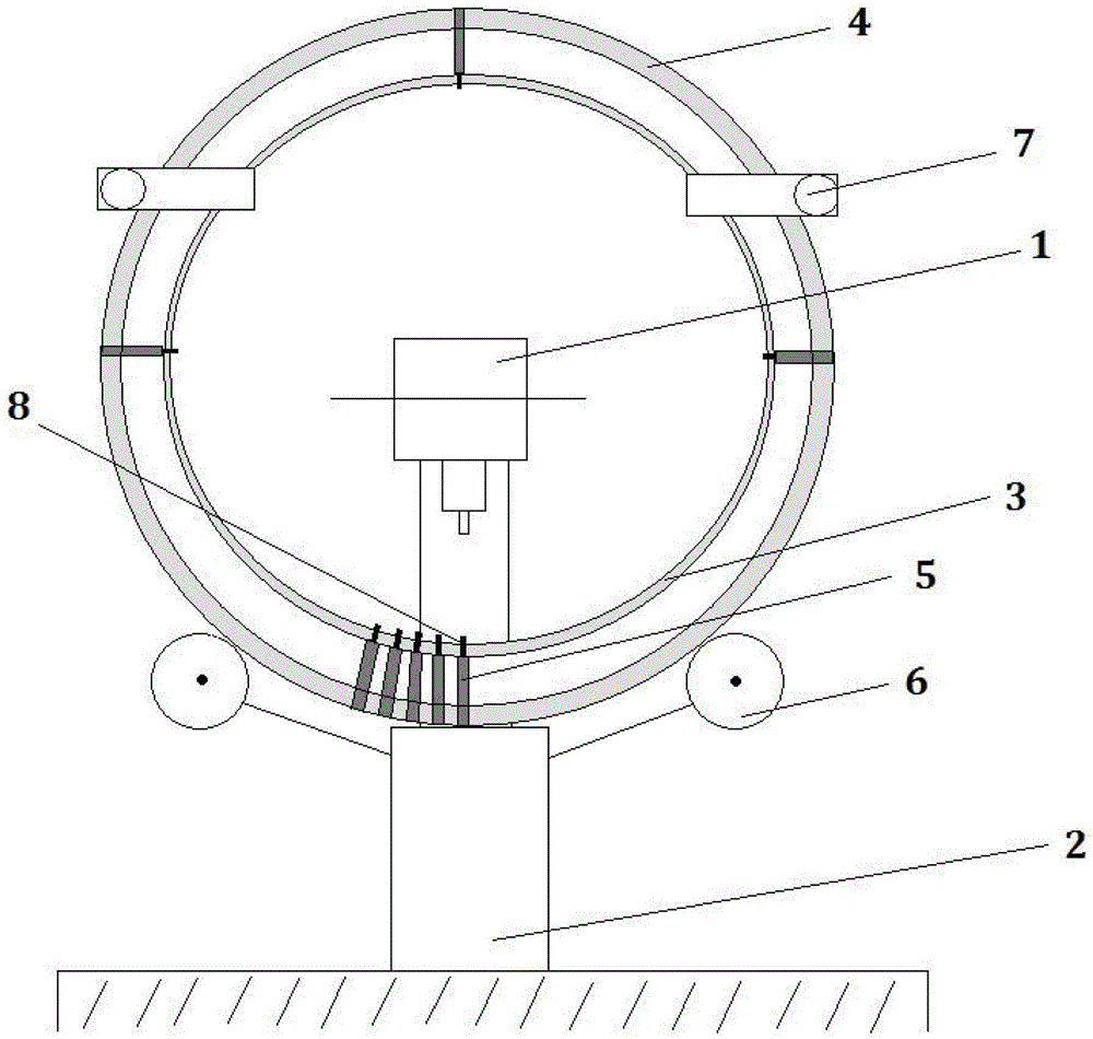
[0009] The method for installing the fixed cover of the stator blade is to insert the blade 5 into the blade wheel 4 freely without any fixing. The actual blade wheel 4 is located laterally on the rotating part 6 and is laterally fixed by the top 7 , while its bottom rests on a solid surface 2 . Simultaneously with the insertion of the blade 5 into the blade wheel 4 , the rivet 8 of the blade 5 is inserted into the shroud 3 so that the blade is supported on the solid surface 2 . The blade is fixed in the shroud 3 by moving the rivet 8 using the rivet head 1 . When the task is completed, the whole blade wheel 4 is rotated by means of the rotating part 6 to install the next rivet 8 . This method is applied until all blades 5 are fixed inside the shroud 3 .

example 2

[0011] The device for implementing the method of mounting the stator blade fixing cover consists of a non-indicative frame with a rotating part 6 mounted on the cover and a top 7 for fixing the blade wheel 4 so that its bottom is always perpendicular to the inserted blade 5 on the solid surface 2 . The rivet head 1 is located in the inner annular housing region 3 .

example 3

[0013] The bladed wheel 4 is placed on the rotating part 6 and on the solid surface 2 . Make sure it goes sideways through the top 7. The blade 5 is inserted into the blade wheel with the rivet 8 towards the center of the wheel. The rivets 8 of the prepared blade 5 are inserted in this way into the holes of the cover 3 prepared in advance. The rivet head 1 is located in the inner area of ​​the blade wheel 4 , and indeed in the inner area of ​​the shroud 3 , the movement of the rivet 8 causes the deformation to fix the shroud to the blade 5 . The blade 5 in this application sits on a solid surface 2 together with the blade wheel 4 on which the blade wheel 4 sits directly. This way, the least amount of dissipative energy transfer is used. In addition, the entire blade wheel is rotated by means of the rotating part 6, in this way the next blade is mounted. Apply this until all blades are secured. When this process is complete, the blade wheel 4 is removed and a number of bla...


PUM


Abstract

A method for securing stator blade fixing covers is performed by the stator blades being fixed in such a way that the blades (5) are inserted into the blade wheel (4) freely without securing, while the blade wheel (4) is placed on the rotating segments (6) and side- secured by the top segments (7) where the blade (5) rivets (8) are inserted into the cover (3) with the blade (5) inserted in the blade wheel (4) standing on the solid surface (2) and being secured in the cover (3) by removing the rivets (8) using the riveting head (1) while the rotating segments (6) perform the entire blade wheel (4) rotation to secure the next rivet (8) and such procedure is applied until all the blades (5) are fixed in the cover (3). A device for implementing the method for securing the stator blade fixing covers is composed of the non - indicated frame with the rotating segments (6) and top segments (7) being placed on it for fixing the blade wheel (4) that always stands with the bottom perpendicularly inserted blade (5) on a solid surface (2) while the riveting head (1) is located in the internal circular cover (3) area.

Description

technical field [0001] The invention relates to a method of mounting a stator blade retainer and a device for carrying out the method. Background technique [0002] The stationary wheel blades are secured to the shroud along its inner diameter. The shroud is not attached to the blade during the machining process, the shroud is fixed to the blade only after the stationary wheel has been inserted and installed in the turbine support on which the stationary wheel is securely fastened. Depending on the actual situation of the blade installation, the protruding rivets on the fixed blades have to be manually extended on individual small cover pieces, in order to allow the cover to be drilled for the prescribed number of rivets. The holes thus drilled are used to insert rivets at the ends of the fixed blades. However, the hole and rivet tolerances were so tight that some rivets had to be pressed into the holes with such force that both the retaining rivets and the actual retainin...

Claims


Application Information

Patent Timeline
Patent Type & Authority Patents(China)
IPC IPC(8): F01D5/22F01D9/04F01D25/28
CPCF01D9/044F01D5/225F01D25/285F05B2240/916F05D2230/50F05D2230/68F05D2250/313F05D2250/35F05D2260/30
Inventor 弗拉斯季米尔·塞德拉切克
Owner 弗拉斯季米尔·塞德拉切克
Why Eureka
Try Eureka