Engine lubricating oil supply system

An oil supply system and engine technology, which is applied in the direction of engine lubrication, engine components, turbine/propulsion lubrication, etc., can solve problems such as the oil supply system not working properly

Inactive Publication Date: 2019-04-19
AECC SICHUAN GAS TURBINE RES INST
View PDF6 Cites 2 Cited by
  • Summary
  • Abstract
  • Description
  • Claims
  • Application Information

AI Technical Summary

Problems solved by technology

[0005] Solve the problem that the fuel supply system cannot work normally due t...

Method used


Image

  • Engine lubricating oil supply system
  • Engine lubricating oil supply system

Examples


Embodiment Construction

[0014] The present invention will be described in further detail below by means of specific embodiments:

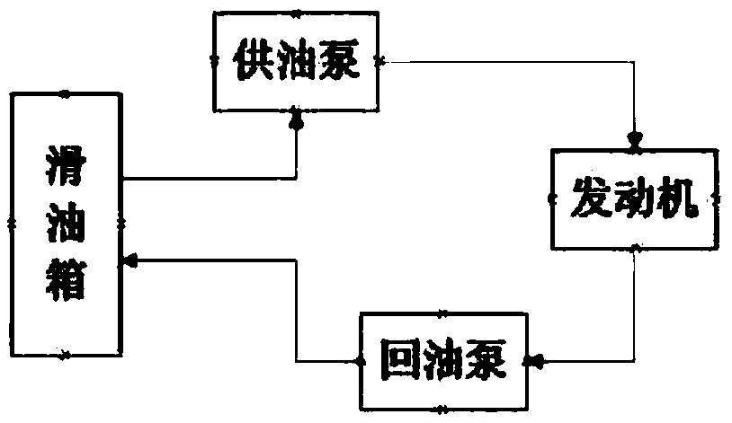
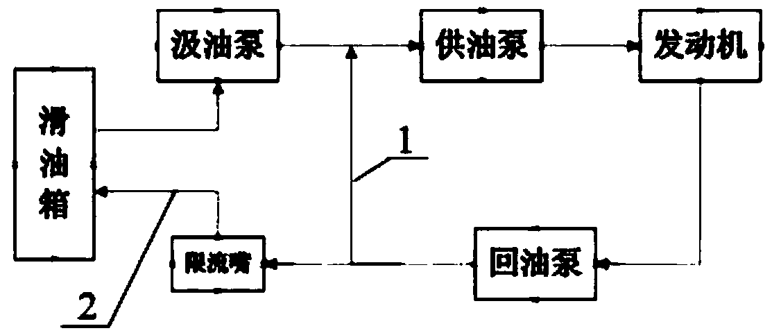
[0015] Such as figure 2 As shown, an engine lubricating oil supply system of the present invention is characterized in that it includes a lubricating oil tank, an oil supply pump and an oil return pump, and is characterized in that it also includes an oil pump, which is arranged in front of the oil supply pump. The flow rate of the oil pump is 50% of the oil supply pump, the lubricating oil in the lubricating oil tank is supplied to the engine after being pressurized by the oil pump and the oil supply pump. After lubricating and cooling the gears and bearings, it is pumped back by the oil return pump. Part of the return oil of the engine enters the oil supply pump along the first flow path 1 and continues to circulate, and part of it flows back to the lubricating oil tank along the second flow path 2. Adjust the restrictor on the top to ensure that the flow of the secon...


PUM


Abstract

The invention discloses an engine lubricating oil supply system which comprises a lubricating oil tank, an oil supply pump and an oil return pump. The system is characterized by further comprising anoil drawing pump arranged before the oil supply pump. The flow amount of the oil drawing pump is 50%-60% of that of the oil supply pump. Lubricating oil of the lubricating oil tank is supplied to an engine after being pressurized through the oil drawing pump and the oil supply pump, and drawn back through the oil return pump after lubricating and cooling a gear, a bearing and the like. A part of return oil of the engine enters the oil supply pump along a first flowing way 1 to continue circulating, a part of the return oil flows back to the lubricating oil tank along a second flowing way 2, the flow amount of the first flowing way 1 and the flow amount of the second flowing way 2 are adjusted through a flow limiting nozzle arranged on the second flowing way 2, and it is ensured that the flow amount of the second flowing way 2 accounts for 80%-90% of the total flow amount of the return oil. According to the engine lubricating oil supply system, the two-stage pump is adopted for pressurizing the lubricating oil, most return oil of the engine does not flow into the lubricating oil tank, and directly enters the oil supply pump to continue circulating, the circulating route is short, preheating of the lubricating oil is benefitted, and starting resistance of the lubricating system is reduced.

Description

technical field [0001] The invention relates to an aero-engine lubricating oil supply system, which is especially suitable for some engines working at high altitude and low Mach number for a long time. Background technique [0002] Aeroengines are mainly based on mechanical transmission of power, and a lubricating oil system needs to be designed to meet the needs of engine lubrication and cooling. Whether the lubricating oil system works normally is related to the safety of the entire engine. When the engine is working at high altitude, since the atmospheric pressure at high altitude decreases continuously with the increase of altitude, in order to ensure the normal operation of the lubricating oil system, measures must be taken to ensure sufficient pressure in the bearing cavity. However, when some engines work at high altitude and low Mach number, the inlet pressure of the engine decreases, the engine state is small, the internal pressure decreases, and the bleed air press...

Claims


Application Information

Patent Timeline
IPC IPC(8): F02C7/06
CPCF02C7/06
Inventor 王敏赵强鄢光荣李贵林潘代锋宋飞金健赵欣周杉
Owner AECC SICHUAN GAS TURBINE RES INST
Why Eureka
Try Eureka