lower feeder

A technology for feeding and feeding ammunition, which is applied in the direction of ammunition supply, offensive equipment, weapon accessories, etc., can solve the problems of infantry robot pan/tilt with variable parameters and difficult debugging, etc., to solve the problem of variable pan/tilt parameters, difficult The effect of loading ammunition and facilitating electronic control debugging

Active Publication Date: 2021-04-27
SOUTHEAST UNIV
View PDF5 Cites 0 Cited by
  • Summary
  • Abstract
  • Description
  • Claims
  • Application Information

AI Technical Summary

Problems solved by technology

[0003] Purpose of the invention: The purpose of the present invention is to provide a lower ammunition feeding device to greatly reduce the weight of the platform of the infantry robot, increase the load capacity, and solve the problem that the parameters of the platform of the infantry robot are variable and difficult to debug

Method used


Image

  • lower feeder
  • lower feeder
  • lower feeder

Examples


Embodiment Construction

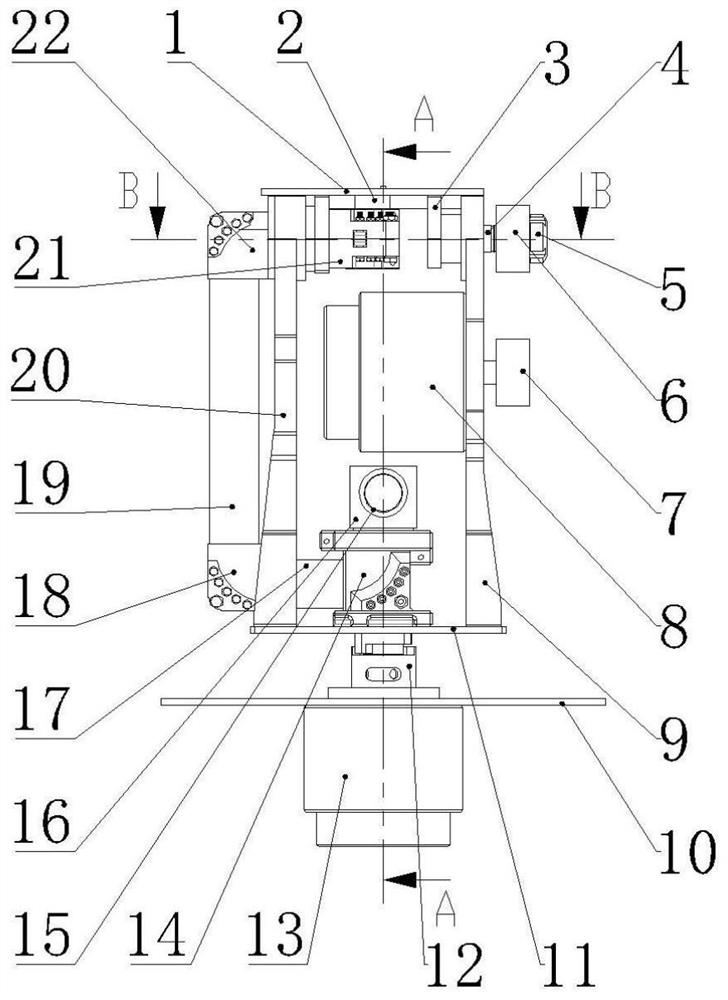
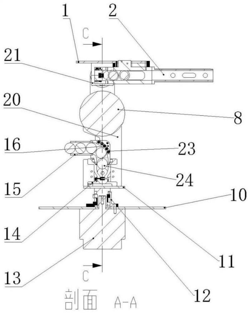
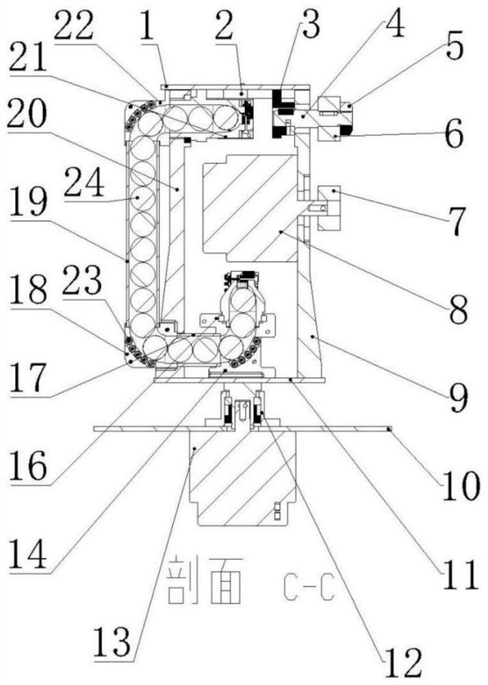
[0014] Such as figure 1 As shown, the present invention includes a pan-tilt upper plate 1, a gun barrel 2, a motor side coupling 3, a synchronous wheel shaft 4, a synchronous wheel stop nut 5, a driven synchronous wheel 6, a driving synchronous wheel 7, an X-axis motor 8, Motor side plate 9, gimbal support plate 10, gimbal lower plate 11, Y-axis coupling 12, Y-axis motor 13, elbow two 14, acrylic tube one 15, elbow one 16, acrylic tube two 17, bend Head 3 18, acrylic tube 3 19, non-motor side plate 20, elbow 5 21, elbow 4 22, elbow bearing 23, 17mm projectile 24 and elbow bolt 25.

[0015] In this embodiment, the Y-axis motor 13 is fixedly connected to the lower plate 11 of the pan-tilt through the Y-axis coupling 12 to realize the horizontal rotation of the pan-tilt. The active synchronous wheel 7 is fixed on the 8-axis of the X-axis motor, and the motor side coupling 3, the driven synchronous wheel 6, and the limit nut 5 of the synchronous wheel are fixed on the synchronous...


PUM


Abstract

The invention belongs to the field of bomb feeding, and discloses a lower bomb feeding device, which includes a Y-axis motor, an X-axis motor, a synchronous wheel shaft, a driven synchronous wheel and a plurality of elbows; each elbow is equipped with a plurality of elbows Bolts and elbow bearings. The elbow bearings can guide the projectile and reduce the friction between the projectile and the track wall. Elbow 1 and elbow 2 are installed concentrically and can rotate relative to each other. Elbow 4 and elbow 5 It is located on both sides of the non-motor side plate and can be rotated relative to each other. The second elbow and the third elbow are connected by the second acrylic tube, and the third elbow and the fourth elbow are connected by the third acrylic tube, which can feed the barrel from bottom to top. Supply projectiles. The invention can reduce the weight of the pan-tilt of the infantry robot, increase the load capacity, and can solve the problem that the parameters of the pan-tilt of the infantry robot are variable and difficult to debug.

Description

technical field [0001] The invention relates to the technical field of bomb feeding from bottom to top, in particular to a bottom bomb feeding device. Background technique [0002] The infantry robots in the MechMaster competition need to rely on the bomb bay to store projectiles. Nowadays, most of the participating teams install the bomb bay on the top of the gimbal, and then directly supply the projectiles to the barrel from the top of the gimbal, but install the bomb bay on the gimbal It will definitely increase the weight of the gimbal, thereby limiting the load capacity, and the parameters of the gimbal will be affected by the number of projectiles in the bomb bay, which will increase the burden of gimbal electronic control debugging. The traditional upper bomb feeding mechanism cannot avoid such problems. Therefore, when making infantry robots, there is an urgent need for a bomb feeding device that can effectively avoid the overweight of the gimbal and reduce the diffi...

Claims


Application Information

Patent Timeline
Patent Type & Authority Patents(China)
IPC IPC(8): F41A9/01
CPCF41A9/01
Inventor 罗荣刘晓军
Owner SOUTHEAST UNIV
Why Eureka
Try Eureka