Bidirectional wavelength division multiplexing optical amplifier device

An amplification device and wavelength division multiplexing technology, applied in the field of bidirectional wavelength division multiplexing optical amplification devices, can solve the problems of incompatibility, low efficiency, polarization sensitivity, etc., and achieve the effect of achieving compatibility

Active Publication Date: 2021-09-07
SHANGHAI JIAOTONG UNIV
View PDF3 Cites 0 Cited by
  • Summary
  • Abstract
  • Description
  • Claims
  • Application Information

AI Technical Summary

Problems solved by technology

This solution needs to insert an isolator for each wavelength channel, which increases the cost of the system, and the amplifier needs to be customized, which is not compatible with the unidirectional optical amplifier in the existing communication network
The Czech education and research network CESNET and others use distributed Raman amplifiers [5, V.Smotlacha and J.Vojtěch, "Time and frequency transfer using amplified optical links," in European Frequency and Time Forum, (2015), 325.] for two-way The transmitted time-frequency signal is optically amplified. Although a single fiber can guarantee the bidirectional symmetry of the link transmission delay, the noise such as Rayleigh scattering will also be amplified multiple times. Polarization sensitivity and other issues

Method used


Image

  • Bidirectional wavelength division multiplexing optical amplifier device
  • Bidirectional wavelength division multiplexing optical amplifier device
  • Bidirectional wavelength division multiplexing optical amplifier device

Examples


Embodiment 1

[0029] Embodiment 1: Bidirectional wavelength division multiplexing optical amplification device for optical fiber time transfer or frequency transfer

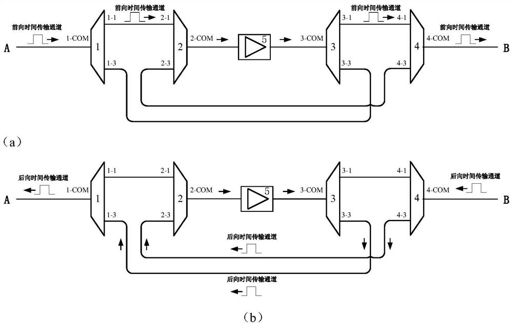
[0030] figure 1 It is a structural schematic diagram of Embodiment 1 of the bidirectional wavelength division multiplexing optical amplification device of the present invention. figure 1 (a) is a schematic diagram of the optical amplification process from A to B, figure 1 (b) Schematic diagram of the optical amplification process from B to A. As can be seen from the figure, embodiment 1 of the bidirectional wavelength division multiplexing optical amplification device used for optical fiber time or frequency transmission according to the present invention comprises: a first division / combiner 1, a multiplexer 2, a unidirectional Optical amplifier 5, wave splitter 3 and second wave splitter / multiplexer 4;

[0031] The multiplexing end 1-COM of the first splitter / combiner 1 is connected to the A-end optical fiber link, and the...

Embodiment 2

[0039] Embodiment 2: A bidirectional wavelength division multiplexing optical amplification device for optical fiber time transfer and having a unidirectional service transmission channel

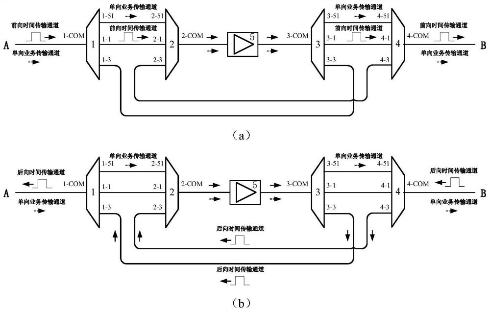
[0040] figure 2 It is a structural schematic diagram of Embodiment 2 of the bidirectional wavelength division multiplexing optical amplification device of the present invention, figure 2 (a) is a schematic diagram of the forward optical signal amplification process, figure 2 (b) Schematic diagram of the backward optical signal amplification process. As can be seen from the figure, the composition of the bidirectional wavelength division multiplexing optical amplifying device of the present embodiment includes sequentially along the forward direction: the first splitter / combiner 1, the multiplexer 2, the one-way optical amplifier 5, the splitter 3 and the first Divider / combiner 4;

[0041] The A-end optical fiber link is connected to the multiplexer 1-COM of the first multiplexer / multi...

Embodiment 3

[0046] Embodiment 3: A bidirectional wavelength division multiplexing optical amplification device for joint transmission of optical fiber time and frequency and having five unidirectional service transmission channels

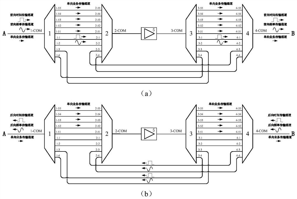
[0047] image 3 It is a structural schematic diagram of Embodiment 3 of the bidirectional wavelength division multiplexing optical amplification device of the present invention, image 3 (a) is a schematic diagram of the forward optical signal amplification process, image 3 (b) Schematic diagram of the backward optical signal amplification process. As can be seen from the figure, the composition of the bidirectional wavelength division multiplexing optical amplifying device of the present embodiment includes sequentially along the forward direction: the first splitter / combiner 1, the multiplexer 2, the one-way optical amplifier 5, the splitter 3 and the first Two dividers / combiners 4; the multiplexer 1-COM of the first divider / combiner 1 is connected to the...


PUM


Abstract

A bidirectional wavelength division multiplexing optical amplification device for optical fiber time-frequency transmission, which sequentially includes a first division / multiplexer, a multiplexer, a one-way optical amplifier, a wavelength division and a second division / multiplexer along the forward direction device. The present invention separates the time / frequency transmission channel from the optical fiber wavelength channel by using a splitter / multiplexer, so that the forward and backward transmission channels on the time / frequency transmission channel and other unidirectional service transmission channels enter the single channel containing the optical isolator. The optical amplifier realizes the two-way amplification of the same fiber and different waves of the optical signal carrying the time / frequency in the bidirectional wavelength division multiplexing time-frequency transmission link, effectively avoiding the multiple amplification of noise such as Rayleigh scattering that affects the time-frequency transmission performance of the optical fiber influences. At the same time, it does not affect the amplification of other unidirectional service transmission channels in the optical fiber, and realizes compatibility with the unidirectional optical amplification in the optical fiber communication network.

Description

technical field [0001] The invention relates to optical fiber time-frequency transmission, in particular to a bidirectional wavelength division multiplexing optical amplification device for optical fiber time-frequency transmission. Background technique [0002] High-precision time-frequency references play an important supporting role in the fields of satellite navigation, precision surveying, geological surveying and mapping, telemedicine and deep space exploration. At present, satellite-based time-frequency transfer technologies, such as GPS Common View (CV) and Satellite Two-way Time-Frequency Comparison (TWSTFT), due to the interference of environmental factors on free space transmission links, the accuracy of time transfer can only reach ns order of magnitude, the stability of frequency transmission can only reach 10 -15 / day. With the continuous development of new technologies, clock sources with higher stability and uncertainty such as optical clocks have been inve...

Claims


Application Information

Patent Timeline
Patent Type & Authority Patents(China)
IPC IPC(8): H04B10/297H04J14/02
CPCH04B10/2971H04J14/0216
Inventor 吴龟灵丁旋刘莹左发兴陈建平
Owner SHANGHAI JIAOTONG UNIV
Why Eureka
Try Eureka