Vehicle thermal management system

A thermal management system and technology for vehicles, applied in the field of thermal management systems for vehicles, can solve problems such as occupying vehicle packaging space, autonomous driving failures, accidents, etc., and achieve the effects of reducing the number of assemblies, improving cooling capacity, and improving productivity

Active Publication Date: 2019-04-19
HANON SYST
View PDF11 Cites 1 Cited by
  • Summary
  • Abstract
  • Description
  • Claims
  • Application Information

AI Technical Summary

Problems solved by technology

[0007] When a conventional thermal management system fails, it cannot cool down the heat source unit stably and continuously, and it will make autonomous driving impossible if the thermal management system is applied to an autonomous vehicle
In the worst case, it could lead to autonomous driving malfunctioning leading to accidents
[0008] Additionally, conventional thermal management systems can be problematic in applicability due to the need to occupy a significant portion of the vehicle's packaging space
In addition, conventional thermal management systems suffer from increased size of the blower if a large amount of cooling performance is required in a small-sized space
[0009] In addition, the conventional thermal management system having a structure for sucking and exhausting outdoor air in one module has another problem that cooling performance and efficiency deteriorate because the heated air is recirculated and sucked in, and if the temperature of the outdoor air High, there are disadvantages in terms of durability and noise due to the high pressure generated in the system

Method used


Image

  • Vehicle thermal management system
  • Vehicle thermal management system
  • Vehicle thermal management system

Examples


Embodiment Construction

[0042] Hereinafter, the technical structure of the thermal management system for a vehicle according to the present invention will be described in detail with reference to the accompanying drawings.

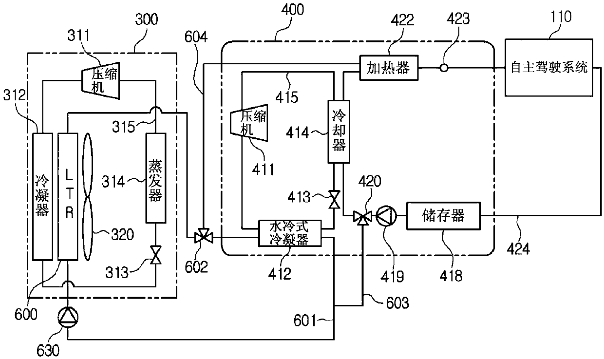
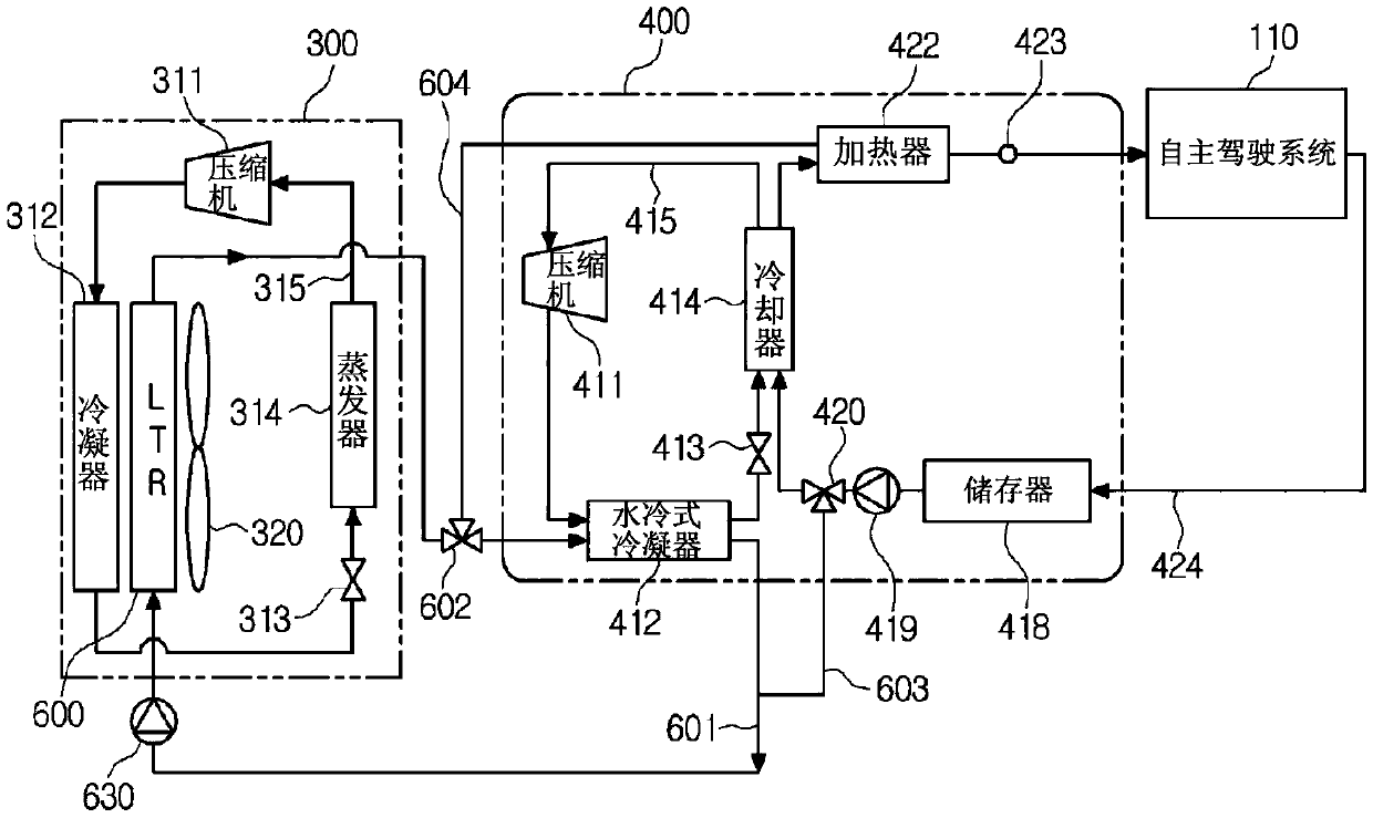
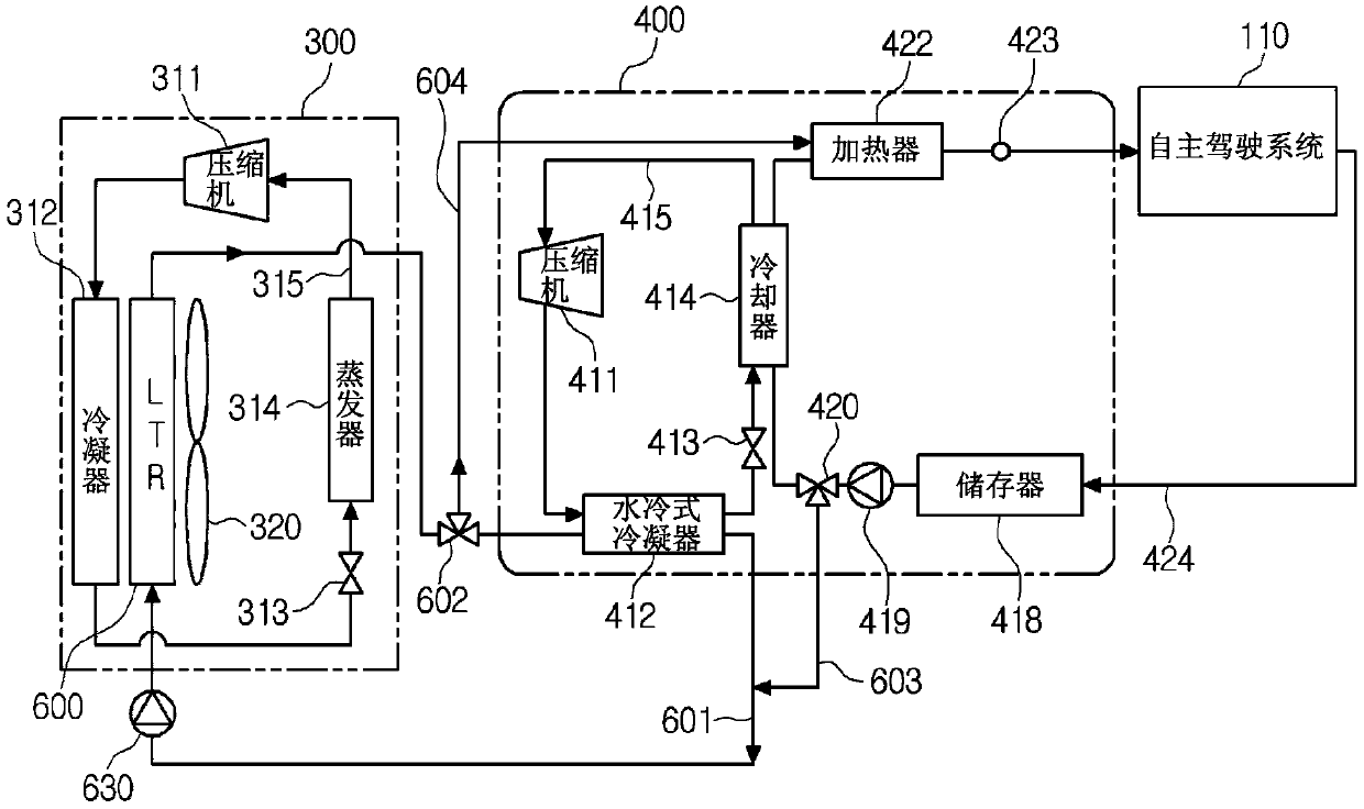
[0043] figure 1 is a diagram of a thermal management system for a vehicle according to a first preferred embodiment of the present invention, figure 2is a diagram showing a cooler cooling mode of the thermal management system for a vehicle according to the first preferred embodiment of the present invention, and image 3 is a diagram showing a radiator cooling mode of the thermal management system for a vehicle according to the first preferred embodiment of the present invention.

[0044] Such as Figure 1 to Figure 3 As shown in , a thermal management system for a vehicle according to a first preferred embodiment of the present invention is used to perform a series of thermal managements to cool or heat electronic components of an autonomous vehicle such as computers, lidars,...


PUM


Abstract

Disclosed is a vehicle thermal management system which is separately provided with the final heat dissipation unit of a cooling system for cooling electronic components required for the autonomous driving of a vehicle, optimizes the modularization of units, and thereby promotes the reduction of a package. The vehicle thermal management system is configured such that: a first compressor which sucksin and compresses a refrigerant and then discharges same in a high-temperature, high-pressure, gaseous state, a condenser for condensing the refrigerant, a first expansion valve for expanding the refrigerant, and a chiller for subjecting the refrigerant to heat exchange with a coolant so as to absorb heat are sequentially provided on a first refrigerant line; the condenser is configured as a water cooling condenser for subjecting the refrigerant to heat exchange with the coolant so as to dissipate heat; the vehicle thermal management system is provided with a first coolant line, which exchanges heat with electronic components and passes through the chiller, and a second coolant line, to which a low-temperature radiator for performing heat exchange between the coolant and air is connectedand which passes through the water cooling condenser; and the coolant exchanges heat with the chiller of the first coolant line or exchanges heat with air by means of the low-temperature radiator connected to the second coolant line.

Description

technical field [0001] The present invention relates to a thermal management system for a vehicle, and more particularly, to a thermal management system for a vehicle capable of cooling or heating an electronic device for an autonomous system. Background technique [0002] Typically, automotive autonomous systems include electronics such as lidar, radar, sensors, and the like. For autonomous driving of the vehicle, a series of thermal managements for cooling or heating the electrical components including the electronic devices is essentially required. [0003] Meanwhile, U.S. Patent No. 7841431 (November 30, 2010) discloses a thermal management system for a vehicle, which includes a power train cooling subsystem, a refrigeration subsystem, a battery cooling subsystem, and heating, ventilation and cooling (HVAC ) subsystem. [0004] A conventional automotive thermal management system includes a cooling subsystem, an HVAC subsystem with a first refrigerant circuit with a hea...

Claims


Application Information

Patent Timeline
Patent Type & Authority Applications(China)
IPC IPC(8): B60H1/00B60H1/32B60H1/22B60K11/02B60R16/03
CPCB60H1/00B60H1/22B60H1/32B60R16/03B60K11/02B60H2001/00307B60H1/32284B60H2001/00928B60H1/143B60H1/32281B60H1/00278B60L58/26B60H1/00885B60H1/00271B60H1/3227B60H1/00807B60H1/00492B60H2001/006B60Y2306/05
Inventor 李海准李城齐陈亨奎
Owner HANON SYST
Why Eureka
Try Eureka