
Automatic feeding and discharging small plate shearing machine

A technology of automatic feeding and shearing machine, which is applied in the direction of shearing device, shearing machine equipment, feeding device, etc., can solve the problem of time-consuming and other problems, and achieve the effect of simple structure and reasonable design.

Pending Publication Date: 2019-04-23
南通航力重工股份有限公司
View PDF0 Cites 3 Cited by
  • Summary
  • Abstract
  • Description
  • Claims
  • Application Information

AI Technical Summary

Problems solved by technology

[0002] When processing small steel rulers or small steel bars, a slitting machine is generally used to separate the coiled steel plates into several small steel plates that meet the width, and then the small steel plates are cut by a small shearing machine to obtain steel bars that meet the width and length. Then process the steel bars to get finished products. At present, it is necessary to manually sort out the small steel bars that are cut and blanked, and check whether they meet the specified width. Those that do not meet the requirements need to be manually removed, which is time-consuming.

Method used


Image

  • Automatic feeding and discharging small plate shearing machine
  • Automatic feeding and discharging small plate shearing machine

Examples


Embodiment Construction

[0017] In order to enhance the understanding of the present invention, the present invention will be further described in detail below in conjunction with the accompanying drawings and embodiments, which are only used to explain the present invention and do not limit the protection scope of the present invention.

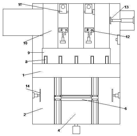
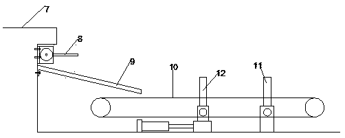
[0018] Such as Figure 1-2 As shown, the present invention is a small-sized plate shearing machine for automatic loading and unloading, comprising a frame 1, a transfer platform 2 and a blanking platform 3 are respectively arranged on the front and rear sides of the frame 1, and the delivery platform 2 is provided with Pushing mechanism, the pushing mechanism comprises lead screw, and lead screw is arranged on the lower end of supporting plate 4 on the conveying platform 2, and supporting block 5 is arranged on the conveying platform 2 on both sides of leading screw, is provided with supporting block 5 middle positions The chute is provided with a push seat on the s...


PUM


Abstract

The invention discloses an automatic feeding and discharging small plate shearing machine. The machine comprises a rack. A conveying table and a discharging table are arranged on the front and rear sides of the rack correspondingly. A pushing mechanism is arranged on the conveying table and comprises a lead screw. The lead screw is arranged at the lower end of a supporting plate. Supporting blocksare arranged in the positions, located on the two sides of the lead screw, of the conveying table correspondingly. Supporting slide grooves are formed in the middles of the supporting blocks correspondingly. A push seat is arranged on slide blocks of the lead screw. The slide blocks are arranged at the two ends of the push seat correspondingly. Mounting seats are arranged at the two ends of a supporting seat. The two ends of the push seat are fixed to the two mounting seats correspondingly. A shearing groove is formed in a workbench. An overturning guide plate and an oblique guide plate are arranged on the side wall of the shearing groove. A plurality of small conveying belts are arranged at the lower end of the oblique guide plate. Two fixed overturning inspection plates and a movable overturning inspection plate are arranged on the discharging table. A push plate is arranged on the lateral side of the discharging table. The automatic feeding and discharging small plate shearing machine is simple in structure and reasonable in design, the widths of sheared steel bars can be detected automatically, and in addition, steel bars with the widths not meeting standards can be rejected.

Description

technical field [0001] The invention relates to a small plate shearing machine, in particular to a small plate shearing machine with automatic loading and unloading. Background technique [0002] When processing small steel rulers or small steel bars, a slitting machine is generally used to separate the coiled steel plates into several small steel plates that meet the width, and then the small steel plates are cut by a small shearing machine to obtain steel bars that meet the width and length. Then the steel bars are processed to obtain finished products. At present, it is necessary to manually sort out the small steel bars that have been cut and blanked, and check whether they meet the specified width. Those that do not meet the requirements need to be manually removed, which is time-consuming. Contents of the invention [0003] In order to solve the above problems, the present invention provides a small shearing machine capable of automatic loading and unloading, and cap...

Claims


Application Information

Patent Timeline
Patent Type & Authority Applications(China)
IPC IPC(8): B21D43/04B23Q7/12B23D15/06
CPCB21D43/04B23Q7/12B23D15/06Y02P70/10
Inventor 夏小新
Owner 南通航力重工股份有限公司
Learn More