
Differential reduction gear, drive mechanism for crane, and shoreside container crane

A technology of differential deceleration and transmission shaft, which is applied in the direction of traveling mechanism, heavy-duty pulley, transportation and packaging, etc., can solve problems such as multiple sets of deceleration devices

Active Publication Date: 2020-06-09
SANY MARINE HEAVY IND
View PDF4 Cites 0 Cited by
  • Summary
  • Abstract
  • Description
  • Claims
  • Application Information

AI Technical Summary

Problems solved by technology

[0004] The purpose of the present invention is to provide a differential speed reduction device to solve the technical problem that multiple sets of speed reduction devices are required for shoreside container cranes in the prior art;
[0005] The object of the present invention is also to provide a driving mechanism for a crane, so as to solve the technical problem in the prior art that the shore container crane needs multiple sets of reduction gears;
[0006] The object of the present invention is also to provide a shore container crane, to solve the technical problem that the shore container crane needs multiple sets of speed reduction devices in the prior art

Method used


Image

  • Differential reduction gear, drive mechanism for crane, and shoreside container crane
  • Differential reduction gear, drive mechanism for crane, and shoreside container crane
  • Differential reduction gear, drive mechanism for crane, and shoreside container crane

Examples


Embodiment 1

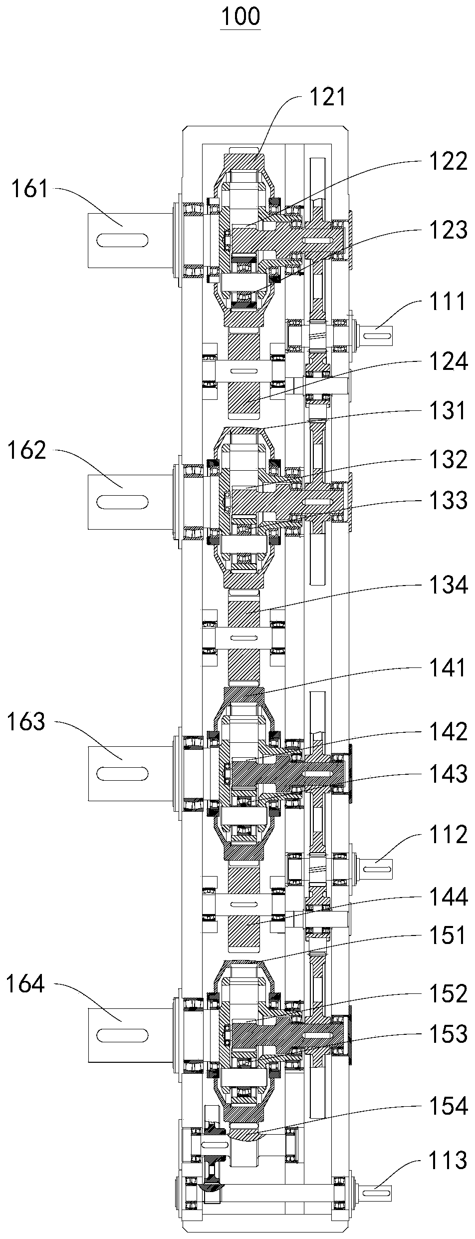
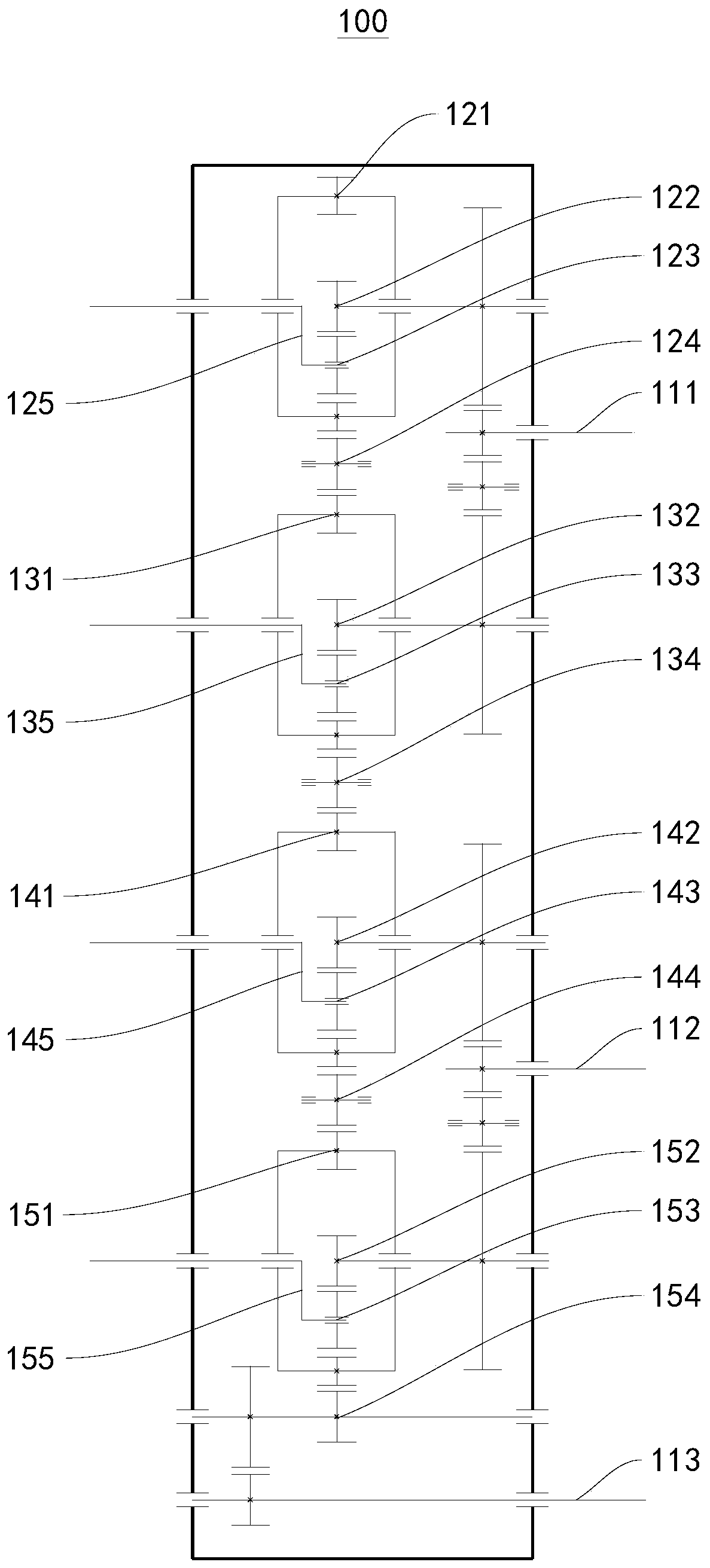
[0075] This embodiment provides a differential reduction device 100, please refer to figure 1 and figure 2 ,

[0076] This differential reduction device 100 includes:

[0077] The first planetary gear 123 series, the first planetary gear 123 series includes the first ring gear 121, the first sun gear 122, the first planetary gear and the first planet carrier 125, the first planetary gear and the first ring gear 121 and the first planetary carrier 125 respectively A sun gear 122 meshes, and the first planet carrier 125 is connected to the first sun gear 122;

[0078] The second planetary gear 133 series, the second planetary gear 133 series includes the second ring gear 131, the second sun gear 132, the second planetary gear and the second planetary carrier 135, the second planetary gear and the second ring gear 131 and the second planetary carrier 135 respectively. The second sun gear 132 meshes, and the second planet carrier 135 is connected to the second sun gear 132;

...

Embodiment 2

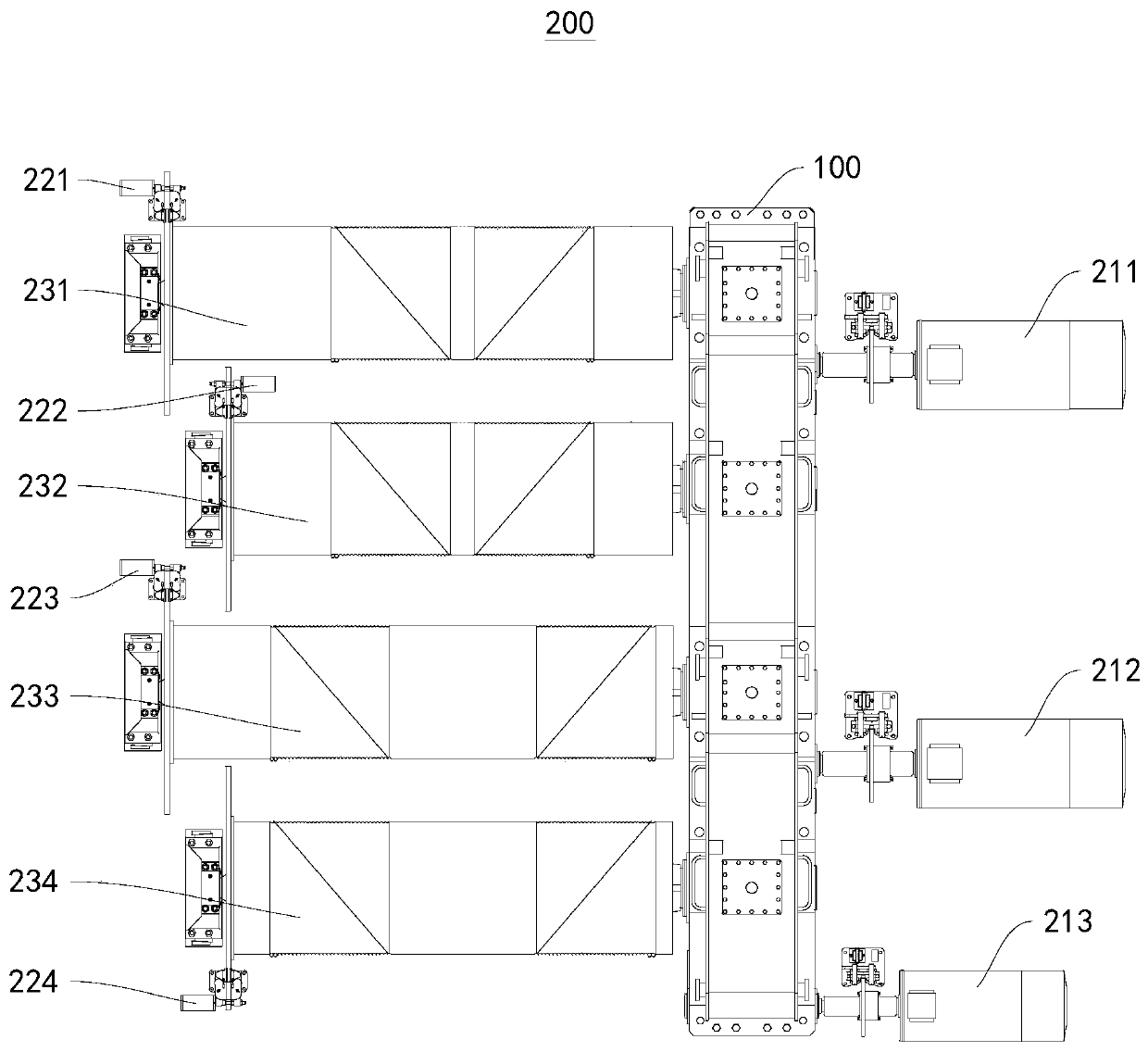
[0110] This embodiment provides a driving mechanism 200 for a crane, please refer to image 3 ,

[0111] The driving mechanism 200 for a crane includes: the differential speed reduction device 100 provided in the first embodiment and,

[0112] The first driving member 211, the first driving member 211 and the first transmission shaft 111 are connected in transmission;

[0113] The second driving member 212, the second driving member 212 and the second transmission shaft 112 are connected in transmission;

[0114] The third driving member 213, the third driving member 213 and the third transmission shaft 113 are connected in transmission;

[0115] The first reel 231, the first reel 231 and the first planet carrier 125 are connected by transmission;

[0116] The second reel 232, the second reel 232 and the second planet carrier 135 are connected by transmission;

[0117] The third reel 233, the third reel 233 and the third planet carrier 145 are connected by transmission;

...

Embodiment 3

[0124] This embodiment provides a shoreside container crane 300, please refer to Figure 4 , Figure 5 , Figure 6 , Figure 7 , Figure 8 as well as Figure 9 ,

[0125] This shoreside container crane 300 includes the crane driving mechanism 200 provided in the first embodiment and,

[0126] The first hanger upper frame 320 has a first connection assembly and a second connection assembly on the first spreader upper frame 320. The first connection assembly is connected to the first reel 231 through the first connection group line, and the second connection assembly is connected through the second connection assembly. The connecting group wire is connected to the second reel 232;

[0127] The second hanger upper frame 340, the second hanger upper frame 340 has a third connection assembly and a fourth connection assembly, the third connection assembly is connected with the third reel 233 through the third connection group line, and the fourth connection assembly is connect...


PUM


Abstract

The invention provides a differential speed reducing device, a driving mechanism for a crane and a quayside container crane, and relates to the technical field of cranes. The differential speed reducing device comprises a first planet gear system; the first planet gear system comprises a first gear ring, a first center gear, a first planet gear and a first planet carrier; the first planet gear isengaged with the first gear ring and the first center gear; the first planet carrier is connected with the first center gear; the differential speed reducing device further comprises a second planet gear system, a third planet gear system and a fourth planet gear system; the first gear ring is in transmission connection with a second gear ring; the second gear ring is in transmission connection with a third gear ring; and the third gear ring is in transmission connection with a fourth gear ring. The differential speed reducing device, the driving mechanism for the crane and the quayside container crane are low in use and maintenance cost.

Description

technical field [0001] The invention relates to the technical field of cranes, in particular to a differential speed reduction device, a driving mechanism for a crane and a shoreside container crane. Background technique [0002] With the rapid development of global shipping, the requirements for the loading and unloading efficiency of the quay container crane are getting higher and higher. The loading and unloading efficiency of the traditional single-box 40-foot quay container crane has reached a technical bottleneck. In order to break through the bottleneck, double 40-foot shore-to-shore container cranes appeared, and the popularity rate is increasing year by year, which is likely to replace them. [0003] At present, the double 40-foot quayside container crane has two sets of hoisting mechanisms and one set of operating mechanisms to drive, that is, the layout of hoisting mechanism 1 + hoisting mechanism 2 + trolley operating mechanism, each mechanism is independent, and...

Claims


Application Information

Patent Timeline
Patent Type & Authority Patents(China)
IPC IPC(8): B66C11/02B66C9/14B66C11/16
CPCB66C9/14B66C11/02B66C11/16
Inventor 叶磊吕国振余诗明
Owner SANY MARINE HEAVY IND
Learn More