Multi-stage water retaining and emptying system for high dam engineering

An emptying system and engineering technology, applied in water conservancy projects, sea area engineering, coastline protection, etc., can solve the problems of increasing the number of gate wells and construction period, complicated setting of flat pressure pipe and water filling pipe, increasing construction difficulty, etc., so as to save construction and construction The effect of reducing cost, reducing the amount of construction work, and reducing the difficulty of construction

Pending Publication Date: 2019-04-23
CHINA POWER CONSRTUCTION GRP GUIYANG SURVEY & DESIGN INST CO LTD
View PDF9 Cites 1 Cited by
  • Summary
  • Abstract
  • Description
  • Claims
  • Application Information

AI Technical Summary

Problems solved by technology

By setting up multi-level gates to share the total water head, and filling water behind the gates at all levels to offset the water retaining head, the water thrust of the gates at all levels is within the conventional design range, which overcomes the existing technical problems of metal structures, but the structure is still There are the following deficiencies: the ventilation pipe is set outside the gate well, which increases the difficulty of construction; the installation of pressure-leveling pipes, air supply pipes, and water-filling pipes is complicated, and some of them lack backup facilities, which may lead to the failure of system leveling; the gate systems at all levels are shared equally by water head , the head gate only shares part of the water head, which increases the number of gate wells and the construction period

Method used


Image

  • Multi-stage water retaining and emptying system for high dam engineering
  • Multi-stage water retaining and emptying system for high dam engineering
  • Multi-stage water retaining and emptying system for high dam engineering

Examples


Embodiment Construction

[0031] The technical solution of the present invention is further described below in conjunction with the accompanying drawings, but the scope of protection is not limited to the description.

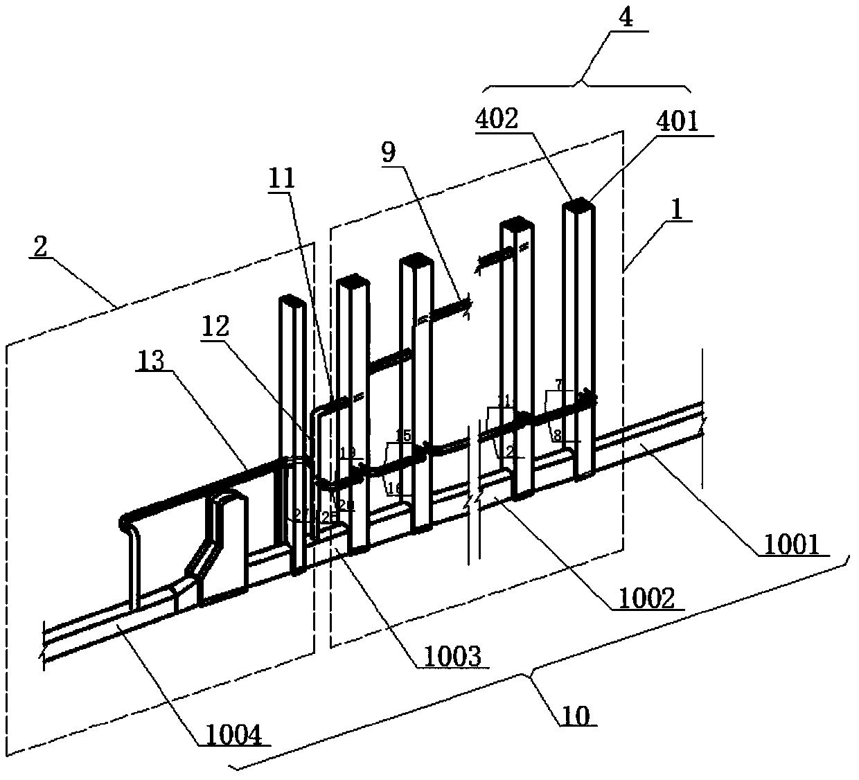
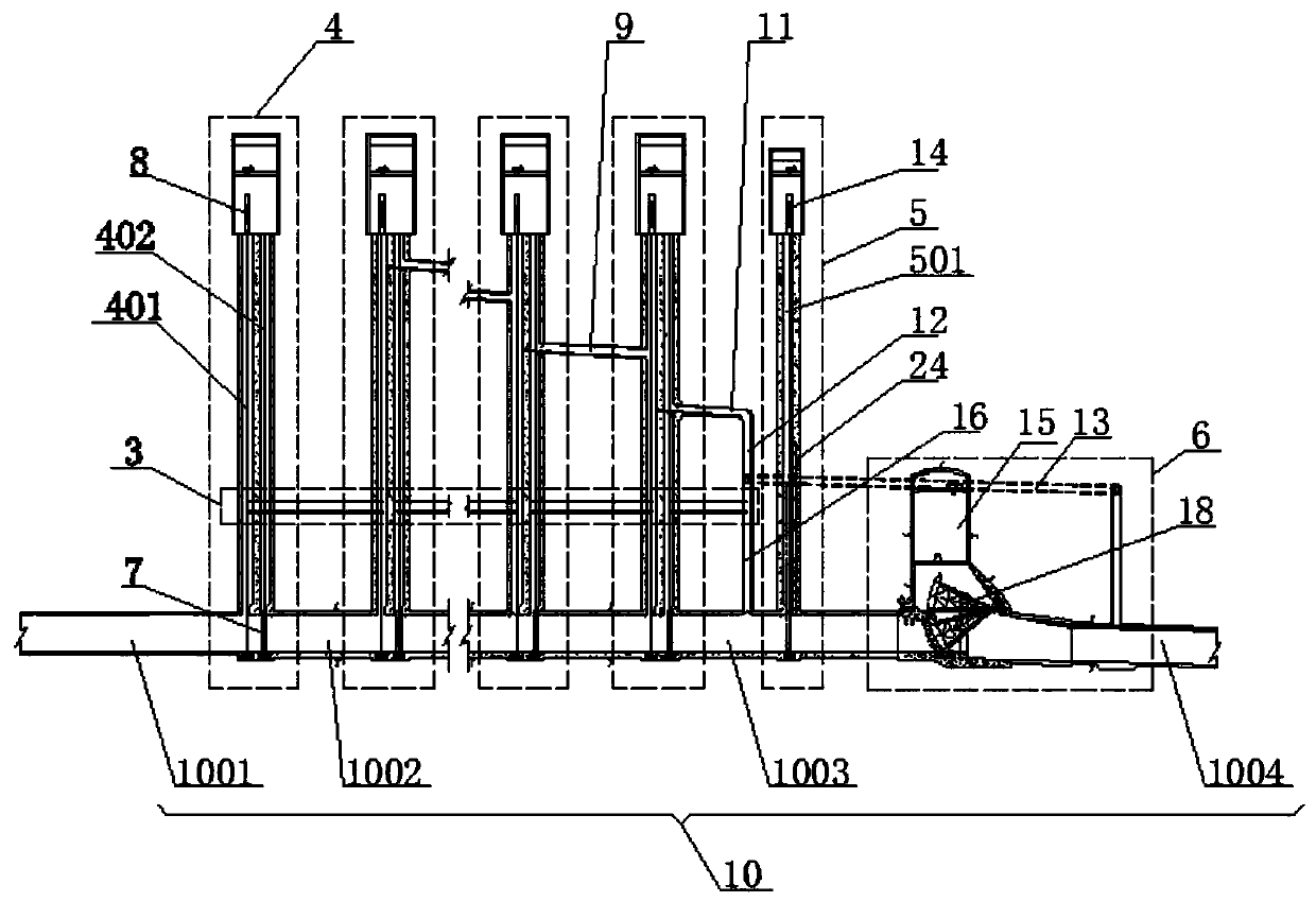
[0032] A kind of multi-stage water retaining and emptying system for high dam engineering of the present invention, such as figure 1 , figure 2 , image 3As shown, it includes a water retaining unit 1, a water discharge unit 2, a flat pressure unit 3 and a tunnel 10. The tunnel 10 is connected to the water source. Along the direction of water flow inside the tunnel 10, the water retaining unit 1 and the water discharge unit 2 are arranged side by side according to an appropriate distance. Above the tunnel 10, the water retaining unit 1 includes n-level water retaining gate devices 4 arranged side by side at appropriate intervals along the water flow direction inside the tunnel 10, and the water discharge unit 2 includes parallel arrangements at appropriate intervals along the water fl...


PUM


Abstract

The invention discloses a multi-stage water retaining and emptying system for high dam engineering. The system comprises a water retaining unit and a water discharging unit which are arranged in sequence along the water flow direction in a tunnel, wherein the water retaining unit is formed by n stages of water retaining gate devices which are arranged at an appropriate spacing; the water discharging unit comprises an accident gate device and a water discharge gate device; and the n stages of water retaining gate devices of the water retaining unit respectively comprise maintenance gate wells and working gate wells which are arranged side by side in the tunnel; flat pressure pipes are arranged side by side at the outer sides of all the gate wells and are respectively communicated with all the maintenance gate wells and the working gate wells; the height, relative to the bottom of the tunnel, of the flat pressure pipe is lower than the water level in the last gate well. By adopting the technical scheme, the water levels in the gate wells are gradually reduced, and the relative water pressure of all the water retaining gate devices is kept stable, so that the resultant force applied to a gate is within the maximum range that the metal structure can bear, and the ability to empty to any depth is achieved; furthermore, due to arrangement of devices such as a blowdown pipe and a water overflow corridor, the safe operation of the emptying system is guaranteed.

Description

technical field [0001] The invention specifically relates to the technical field of water conservancy and hydropower engineering, in particular to a multi-stage water retaining and venting system used in high dam projects. Background technique [0002] The high dam project has brought huge energy benefits to my country's economic and social development, and the venting technology of the project is an important guarantee for its stable and safe operation. However, at present, most 300m-level high dam projects can only be vented to a water depth of about 105m through spillways, spillway tunnels, and vent holes. Therefore, it is necessary to invent a technology suitable for deeper venting to meet the venting operation requirements of today's high dam projects. [0003] In order to meet the operation requirements of the 300m-level high dam project, the Chinese patent with publication number CN105220659B discloses a high dam reservoir ultra-deep water retaining venting system an...

Claims


Application Information

Patent Timeline
Patent Type & Authority Applications(China)
IPC IPC(8): E02B8/04E02B7/20E02B8/06
CPCE02B7/20E02B8/04E02B8/06
Inventor 杨家修杜帅群湛正刚李晓彬郑雪玉鲍伟
Owner CHINA POWER CONSRTUCTION GRP GUIYANG SURVEY & DESIGN INST CO LTD
Why Eureka
Try Eureka