Wind power generator set

A technology for wind turbines and fans, which is applied to wind turbines, wind energy power generation, engines, etc., can solve the problems of high construction requirements for installing water-cooling pipes and leakage of coolant.

Active Publication Date: 2019-04-23
ZHEJIANG UNIV +1
View PDF6 Cites 4 Cited by
  • Summary
  • Abstract
  • Description
  • Claims
  • Application Information

AI Technical Summary

Problems solved by technology

[0004] The technical problem to be solved by the present invention is to provide a wind power generating set in order to overcome the defects that the bearing cooling method of the wind power generating set in the prior art causes a temperature gradient on the surface of the bearing, or the installation of the water-cooled pipe requires high construction requirements, and the coolant may leak.

Method used


Image

  • Wind power generator set
  • Wind power generator set
  • Wind power generator set

Examples


Embodiment 1

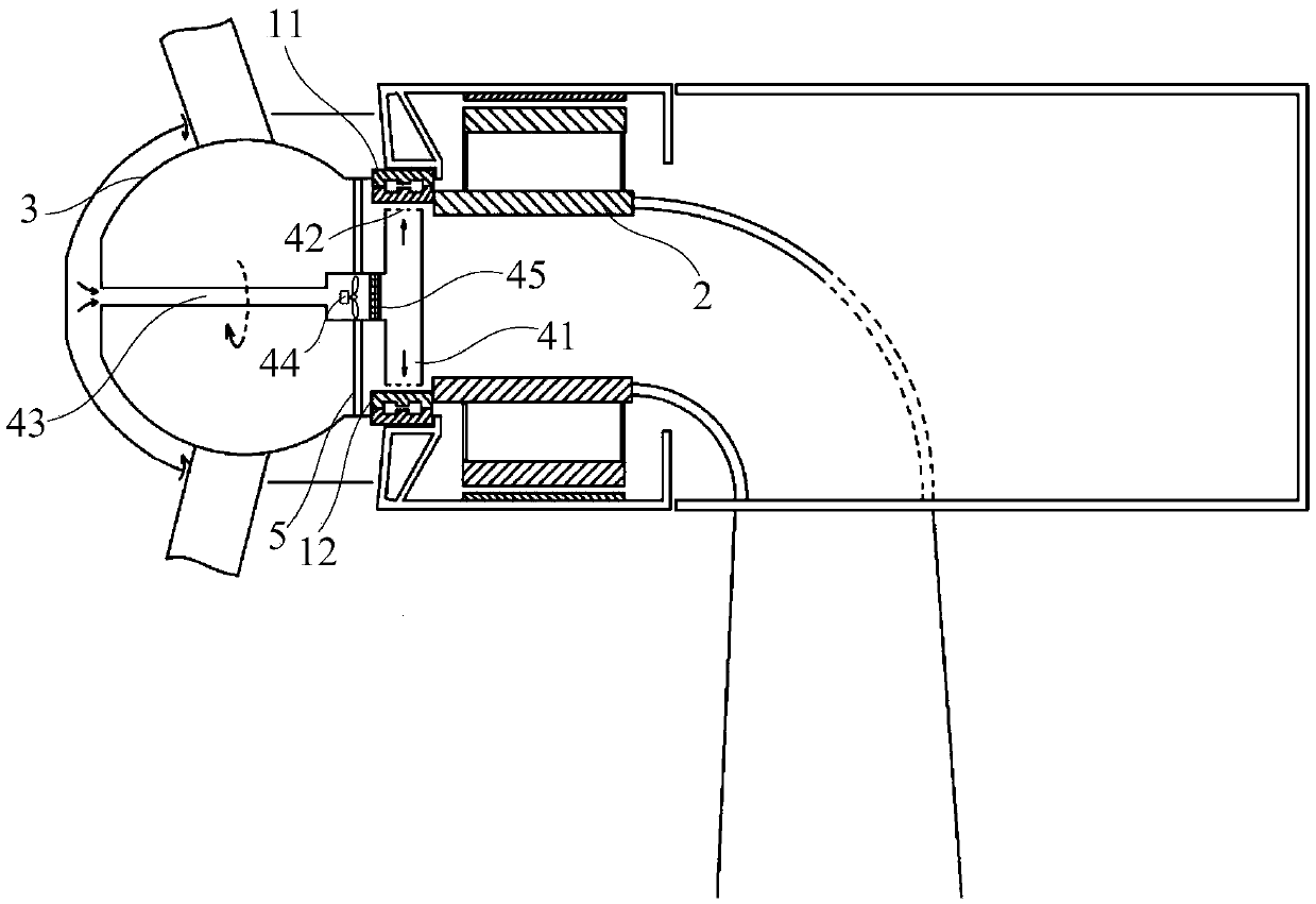
[0045] Such as figure 1 As shown, the present invention provides a wind power generating set, which includes a bearing system, and the bearing system includes a bearing outer ring 11 and a bearing inner ring 12 . The wind power generating set also includes a fixed shaft 2 and a hub 3, the fixed shaft 2 is fixed to the bearing inner ring 12, and the hub 3 is fixed to the bearing outer ring 11. The wind power generating set also includes an air cooling system, which includes an air outlet pipeline 41 and an air inlet pipeline 43, the air outlet pipeline 41 is located in a radial direction of the bearing inner ring 12, and one end thereof is aligned with the bearing inner ring 12 The inner side surface of the bearing inner ring 12 has a partial gap. The air outlet pipeline 41 can rotate around the central point of the bearing inner ring 12 . Preferably, the wind power generating set is provided with two air outlet pipelines 41, one end of the two air outlet pipelines 41 is loca...

Embodiment 2

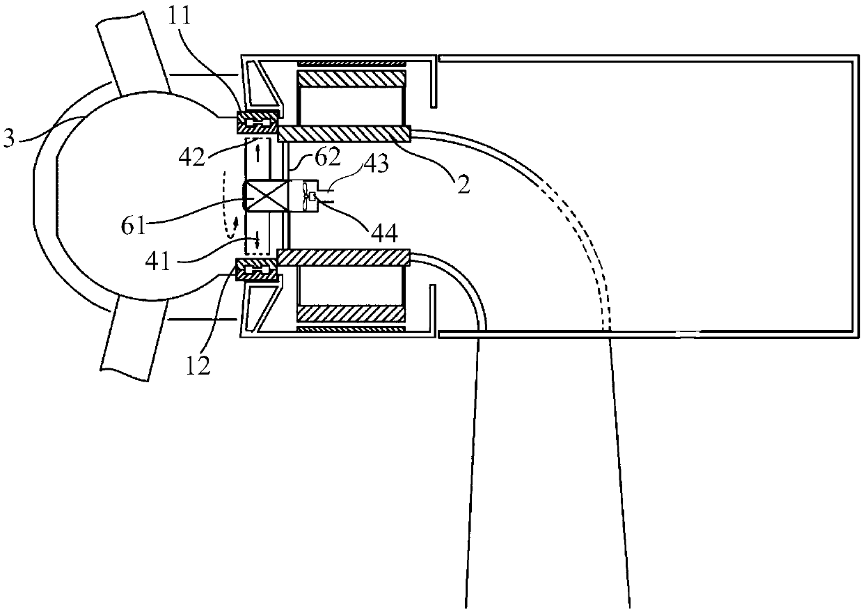
[0051] Such as figure 2 As shown, the structure of this embodiment is basically the same as that of Embodiment 1, and the difference is that the air cooling system also includes a driving device, which includes two support rods 62 and a drive bearing 61, and one end of the support rod 62 is welded On the fixed shaft 2, the other end is connected with a drive bearing 61. The driving device also includes a motor connected inside the driving bearing 61 for driving the driving bearing 61 to rotate. The drive bearing 61 is located at the center point of the bearing inner ring 12 and can rotate around the center point. One end of the air inlet pipeline 43 is connected and fixed to the drive bearing 61 , and the other end is located at the inner space of the nacelle of the wind power generating set.

[0052] An electric control device is also installed on the driving bearing 61, and the rotating speed of the driving bearing 61 is controlled by controlling the motor. During use, t...

Embodiment 3

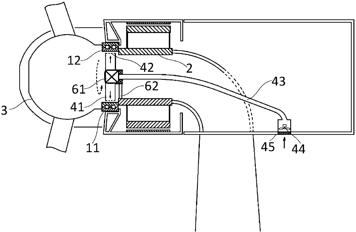
[0056] Such as image 3 As shown, the structure of this embodiment is basically the same as that of Embodiment 2, the difference is that one end of the air inlet pipeline 43 is connected and fixed to the drive bearing 61, and the other end of the air inlet pipeline 43 is welded to the wind power generating set cabin wall.

[0057] When the system of the wind power generating set starts to run, after the surface temperature of the bearing inner ring 12 rises to a certain level, the driving device is turned on, so that the air cooling system starts to rotate around the center point of the bearing inner ring 12, and then drives the air outlet pipe The circuit 41 rotates, and then the fan device 44 is turned on, and the external cooling air is extracted through the air inlet pipe 43, and then sprayed on the surface of the bearing inner ring 12 to achieve the effect of cooling.


PUM


Abstract

The invention provides a wind power generator set. The wind power generator set includes a bearing system, a fixing shaft and a hub, wherein the bearing system includes an outer bearing ring and an inner bearing ring; the fixing shaft is connected with the inner bearing ring; and the hub is connected with the outer bearing ring. The wind power generator set is characterized in that the wind powergenerator set further comprises an air cooling system; the air cooling system includes an air outlet pipeline; the air outlet pipeline is located in the radial direction of the inner bearing ring; andthe air outlet pipeline can be rotatable around the center point position of the inner bearing ring. Air pipelines are used in the wind power generator set to circumferentially eject inner bearing rings by 360 degrees; bearing temperature and circumferential temperature gradient are effectively controlled; coolant is not needed; the process is simple; because the air is sucked from the outside, abearing is cooled while the inner cavity of the hub generates air convection; heat dissipation is enhanced; the abnormal operation of the internal electrical equipment due to excessive temperature isavoided; and at the same time, the wind power generator set also features cabin ventilation to save an additional cabin ventilation device.

Description

technical field [0001] The invention relates to the field of wind power generation, in particular to a wind power generating set. Background technique [0002] In the field of wind power generation, the enlargement of wind turbines is the current development trend, and the enlargement of wind turbines will inevitably require the enlargement of bearings, so at the same time, the load of bearings is also increasing, which puts forward more requirements for the safe operation of bearings. Serious challenges. During the operation of the bearing, the operating temperature is an important factor affecting the safe operation of the bearing. The bearing generates heat during operation, which needs to be dissipated through the cooling system, otherwise the bearing will run at a very high temperature, which will affect the service life. [0003] At present, there are two kinds of bearing cooling methods: air cooling and water cooling. In the air cooling method, heat pipe cooling com...

Claims


Application Information

Patent Timeline
Patent Type & Authority Applications(China)
IPC IPC(8): F03D80/60F03D80/70
CPCF03D80/60F03D80/70Y02E10/72
Inventor 施杨吴立建闻汇杨飞崔明许爽杨红全王伶俐方攸同
Owner ZHEJIANG UNIV
Why Eureka
Try Eureka