Polarized light orientation method of unmanned plane under cloudy conditions

A polarized light, machine cloudy technology, applied in computer parts, instruments, characters and pattern recognition, etc., can solve problems such as reduced accuracy, unsuitable cloudy weather, etc., to improve segmentation accuracy, improve adaptability and positioning measurement accuracy, Use a wide range of effects

Active Publication Date: 2019-04-23
NAT UNIV OF DEFENSE TECH
View PDF5 Cites 4 Cited by
  • Summary
  • Abstract
  • Description
  • Claims
  • Application Information

AI Technical Summary

Problems solved by technology

[0005] The present invention provides a polarized light orientation method, system and polarized light sensor for unmanned aerial vehicles under cloudy conditions, which are used to overcome the defects

Method used


Image

  • Polarized light orientation method of unmanned plane under cloudy conditions
  • Polarized light orientation method of unmanned plane under cloudy conditions
  • Polarized light orientation method of unmanned plane under cloudy conditions

Examples


Embodiment 1

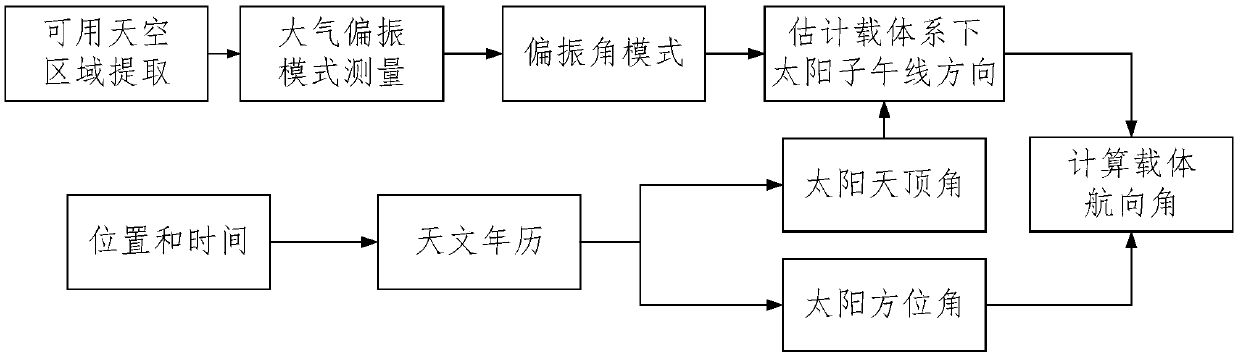
[0031] as attached figure 1 As shown, a polarized light orientation method for unmanned aerial vehicles under cloudy conditions mainly includes the following steps:

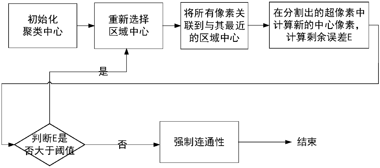
[0032] Step 1, extract the most distinguishable color feature from all pixels in the collected image;

[0033] Firstly, the images collected by the UAV camera are processed. There are many of these images, including different viewing angles and different positions. It is necessary to screen the images that are most conducive to the orientation of polarized light. In terms of distinction, images with higher discrimination or recognition can repeatedly reflect the directional characteristics of polarized light. The screening standard is color features. The color features here can be combined and transformed according to color contrast, brightness, and channel parameter values. . In a specific embodiment of the present invention, the most distinguishable color features are extracted according to different color ch...

Embodiment 2

[0123] The embodiment of the present invention also provides a polarized light orientation system under the cloudy condition of the drone, including a processor and a memory, the memory stores a polarized light orientation program under the cloudy condition of the drone, and the processor is running the drone The steps in any of the above embodiments of the polarized light directional method are executed during the polarized light directional program under cloudy conditions.

Embodiment 3

[0125] An embodiment of the present invention also provides a polarized light sensor, including a polarized light orientation system for an unmanned aerial vehicle under cloudy conditions.


PUM


Abstract

The invention discloses a polarized light orientation method of an unmanned plane under the cloudy conditions. The method comprises the following steps of extracting color features with the highest distinguishing degree from all pixel points in a collected image; performing super pixel division on the images; obtaining a plurality of super pixel blocks; distinguishing the sky regions and cloud layers for polarization orientation from the divided images according to the color features through clustering; by using an expansion method, processing the images; reducing the extracted sky region; eliminating the cloud layer edge interference; according to the Rayleigh scattering model and images, building a relationship model of a sun direction vector and polarization angle and the solar zenith angle under the unmanned vector coordinate system; according to the azimuth angle and sun meridian line direction and relationship model, obtaining the course angle of the unmanned plane vector in thegeographic coordinate system. The problem of poor adaptability in the prior art is solved; the positioning precision of the unmanned plane under the cloudy conditions can be improved.

Description

technical field [0001] The invention relates to the technical field of unmanned aerial vehicle orientation, in particular to a polarized light orientation method and system for an unmanned aerial vehicle under cloudy conditions, and a polarized light navigation sensor. Background technique [0002] Classic navigation technology has come a long way. The inertial navigation system is the most typical and commonly used autonomous navigation technology. It has the advantages of strong anti-interference, complete navigation information, and strong real-time performance. High-precision navigation requirements for long-duration motion platforms. Satellite navigation has the advantages of all-weather, high precision (and the navigation accuracy does not change with time), and the integration of navigation, positioning and timing. It is the most widely used navigation technology, but it has not fundamentally solved the security problem of the navigation system, and it is easy to be ...

Claims


Application Information

Patent Timeline
IPC IPC(8): G01C21/20G06K9/46G06K9/62
CPCG01C21/20G06V10/56G06F18/23213
Inventor 胡小平吴雪松何晓峰张礼廉范晨毛军蔡宇
Owner NAT UNIV OF DEFENSE TECH
Why Eureka
Try Eureka