Device and method for testing LED (Light Emitting Diode) aging under multiple physics fields

A technology of aging test and multi-physics field, applied in the direction of measuring device, vibration test, optical instrument test, etc., can solve the problems of optical parameter test error, lack of reliability test, quality difference, etc., and achieve the goal of reducing the impact of high temperature Effect

Inactive Publication Date: 2019-04-23
HOHAI UNIV CHANGZHOU
View PDF14 Cites 2 Cited by
  • Summary
  • Abstract
  • Description
  • Claims
  • Application Information

AI Technical Summary

Problems solved by technology

[0002] Compared with ordinary light sources, LED has the advantages of low power consumption and long life, which makes it greatly developed in lighting and other fields; however, the quality of LEDs often varies in the market, and the lack of advanced technology for reliability testing makes Consumers lack confidence in the further promotion and application of the LED market
[0003] The test devices in the prior art can usually only test one performance of LEDs in a single environment. For multi-performance tests of LEDs in different environments, various test devices must be used respectively, which brings a lot of inconvenience to LED testing.
At present, there are also some devices that can comprehensively test the performance of LEDs in different environments. For example, the LED testing device designed by Yang Yaowu can test the performance parameters of LEDs such as light, color and electricity under different temperatures and vibration environments. See patent CN104459569A for details; but This design exposes the optical instrument to the environment of temperature shock, and due to the influence of vibration, it will lead to the measurement error of optical parameters

Method used


Image

  • Device and method for testing LED (Light Emitting Diode) aging under multiple physics fields
  • Device and method for testing LED (Light Emitting Diode) aging under multiple physics fields
  • Device and method for testing LED (Light Emitting Diode) aging under multiple physics fields

Examples


Embodiment Construction

[0019] The present invention will be further described below in conjunction with the accompanying drawings.

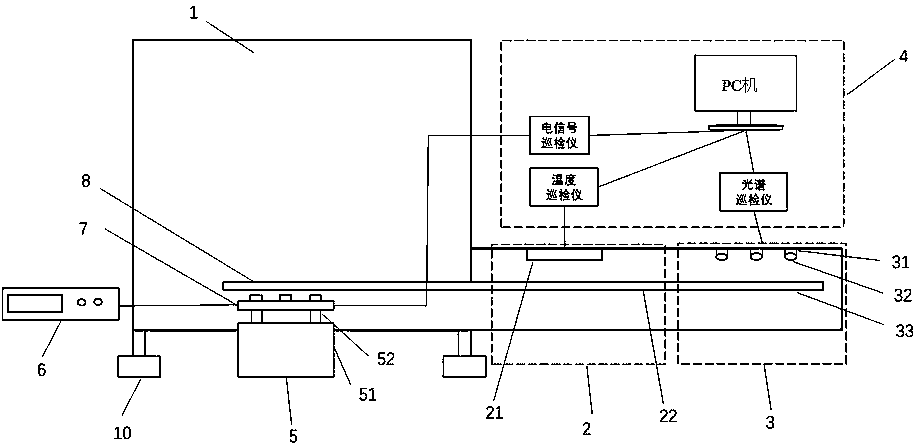
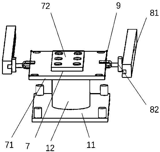
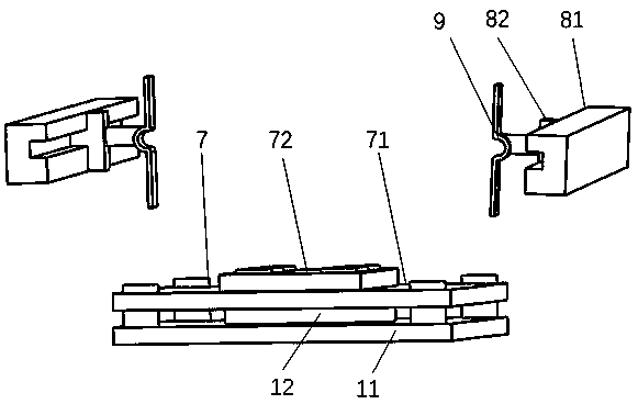
[0020] Such as Figure 1~Figure 3 As shown, a multi-physics field LED aging test device includes an aging module, a test module and a sliding device. The aging module includes a high-temperature aging box 1, a vibration device 5, and a circuit board device 7. The vibration device 5 includes a vibrator 51 and a support column 52. The circuit board device 7 includes a circuit board support plate 71 and a circuit board 72. Several LED chips are evenly distributed on the circuit board 72 , and six LED chips are evenly distributed on the circuit board 72 in this embodiment. The lower side of the circuit board support plate 71 is connected to the fixed support plate 11 through the telescopic mechanism 12, and the fixed support plate 11 is fixedly connected to the support column 52 of the vibrating device. The telescoping mechanism 12 may be a small electric jack device. F...


PUM


Abstract

The invention discloses a device and a method for testing LED (Light Emitting Diode) aging under multiple physics fields. The device mainly comprises a vibrating device, a sliding device, a fixture, acircuit board device, an infrared heat signal collecting module, an integrating sphere optical signal collecting module and a data collecting module, wherein the sliding device is capable of moving the aged circuit board device to the infrared heat signal collecting module and the integrating sphere optical signal collecting module for carrying out signal collection, and then data can be sent toa PC (Personal Computer) of the data collecting module. According to the device for testing the LED aging, provided by the invention, online testing can be carried out after the device is aged under the multiple physical fields such as current, high temperature and vibrating environments, optical, electric and thermal signals of an LED can be online collected, and the using performance of the LEDunder different aging environments can be comprehensively reflected.

Description

technical field [0001] The invention relates to a multi-physics field LED aging test device and method, belonging to the technical field of LED online testing. Background technique [0002] Compared with ordinary light sources, LED has the advantages of low power consumption and long life, which makes it greatly developed in lighting and other fields; however, the quality of LEDs often varies in the market, and the lack of advanced technology for reliability testing makes Consumers lack confidence in the further promotion and application of the LED market. [0003] The testing devices in the prior art can usually only test one performance of LEDs in a single environment. For multi-performance testing of LEDs in different environments, various testing devices must be used respectively, which brings a lot of inconvenience to LED testing. At present, there are also some devices that can comprehensively test the performance of LEDs in different environments. For example, the LE...

Claims


Application Information

Patent Timeline
Patent Type & Authority Applications(China)
IPC IPC(8): G01R31/26G01M7/02G01M11/02G01M11/08
CPCG01M7/00G01M11/00G01M11/08G01R31/2642
Inventor 刘杰樊嘉杰王平吴伟子
Owner HOHAI UNIV CHANGZHOU
Why Eureka
Try Eureka