
Display device and manufacturing method thereof

A technology for a display device and a manufacturing method, which is applied in nonlinear optics, instruments, optics, etc., can solve the problems of short service life of display devices, and achieve the effect of solving short service life

Inactive Publication Date: 2019-04-23
NANJING CEC PANDA LCD TECH
View PDF5 Cites 3 Cited by
  • Summary
  • Abstract
  • Description
  • Claims
  • Application Information

AI Technical Summary

Problems solved by technology

[0005] In order to solve the above problems, a display device and its manufacturing method are provided. In the method, a multi-layer plastic frame is provided in the non-display area of ​​the display device, a slit area is formed between the plastic frames, and a gap is opened on the plastic frame to allow redundant The liquid glue can enter the slit area from the gap, and the air inside the display device can also be discharged through the slit area. The requirements for the production environment are not high. The gaps of the multi-layer glue frame are set on different sides, and the multi-layer glue frame is used to prevent water vapor. Enter the inside of the display device from the environment in which the display device is used, solving the problem of short service life of the display device

Method used


Image

  • Display device and manufacturing method thereof
  • Display device and manufacturing method thereof
  • Display device and manufacturing method thereof

Examples


Embodiment 1

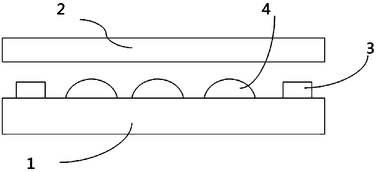
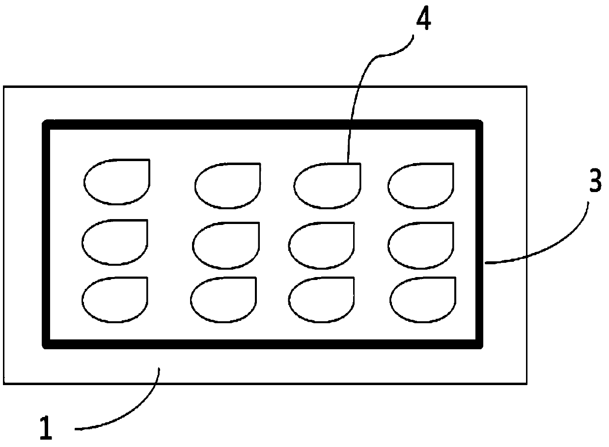
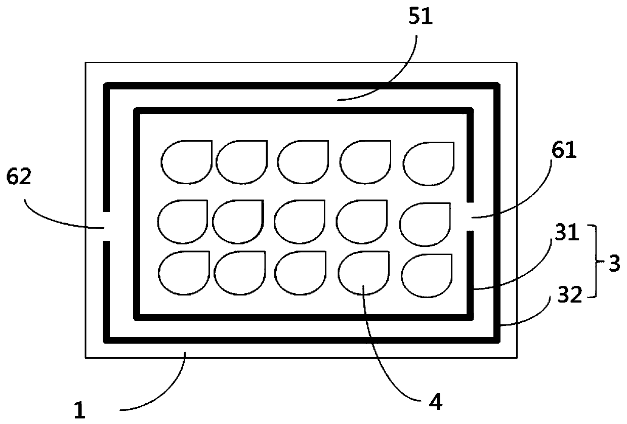
[0036] Figure 3 to Figure 5 It is a structural schematic diagram of the first embodiment of the present invention, a display device includes: a display panel 1 and a cover plate (not shown in the figure) arranged oppositely, and a liquid adhesive layer 4 arranged between the display panel 1 and the cover plate, the The display panel 1 and the cover plate are adhered by a frame glue 3 , the display panel 1 includes a display area and a non-display area surrounding the display area, and the glue frame 3 is arranged in the non-display area.

[0037] The plastic frame 3 includes a first plastic frame 31 and a second plastic frame 32, the first plastic frame 31 and the second plastic frame 32 are arranged concentrically, the second rubber frame 32 is arranged on the outside of the first rubber frame 31, and the first plastic frame A first slit 51 is formed between the frame 31 and the second rubber frame 32, a first gap 61 is provided on the first rubber frame 31, a second gap 62 ...

Embodiment 2

[0041] Figure 6 It is a structural schematic diagram of the second embodiment of the present invention, a display device includes: a display panel 1 and a cover plate (not shown in the figure) arranged oppositely, and a liquid adhesive layer 4 arranged between the display panel 1 and the cover plate, the The display panel 1 and the cover plate are adhered by a frame glue 3 , the display panel 1 includes a display area and a non-display area surrounding the display area, and the glue frame 3 is arranged in the non-display area.

[0042] The plastic frame 3 includes a first plastic frame 31 and a second plastic frame 32, the first plastic frame 31 and the second plastic frame 32 are arranged concentrically, the second rubber frame 32 is arranged on the outside of the first rubber frame 31, and the first plastic frame A first slit 51 is formed between the frame 31 and the second rubber frame 32, a first notch 61 is respectively arranged on the upper frame and the lower frame of th...

Embodiment 3

[0046] Figure 7 It is a structural schematic diagram of the third embodiment of the present invention, a display device includes: a display panel 1 and a cover plate (not shown in the figure) arranged oppositely, and a liquid adhesive layer 4 arranged between the display panel 1 and the cover plate, the The display panel 1 and the cover plate are adhered by a frame glue 3 , the display panel 1 includes a display area and a non-display area surrounding the display area, and the glue frame 3 is arranged in the non-display area.

[0047] The plastic frame 3 includes a first plastic frame 31 and a second plastic frame 32, the first plastic frame 31 and the second plastic frame 32 are arranged concentrically, the second rubber frame 32 is arranged on the outside of the first rubber frame 31, and the first plastic frame A first slit 51 is formed between the frame 31 and the second plastic frame 32 , and a first notch 61 is respectively provided on the upper frame and the lower fram...


PUM


Abstract

The invention discloses a display device and a manufacturing method thereof, and belongs to the technical field of liquid crystal display. The display device comprises a display panel, a cover plate and a liquid glue layer, wherein the display panel and the cover plate are in opposite arrangement; the liquid glue layer is arranged between the display panel and the cover plate; the display panel and the cover plate are attached through a rubber frame; the rubber frame at least comprises a first rubber frame and a second rubber frame; the first rubber frame and the second rubber frame are in concentric arrangement; a first narrow seam is formed between the first rubber frame and the second rubber frame; at least one first notch is formed in the first rubber frame; through the arrangement ofthe multilayer rubber frame, the narrow seam is formed between the rubber frames; the notch is formed in the rubber frame; during pressing operation, excessive liquid glue can enter the narrow seam region from the notch; air inside the display device can be exhausted through the narrow seam region; the requirements on production environment are not high; the notches of multilayer rubber frames areformed in different sides; through the multilayer rubber frames, water steam is prevented from entering the inside of the display device from the use environment of the display device; the problem ofshort service life of the display device is solved.

Description

technical field [0001] The invention relates to the technical field of liquid crystal display, in particular to a fully laminated display device and a manufacturing method thereof. Background technique [0002] Liquid crystal display products are widely used in daily life. With the popularization in daily life, the demand for products is large. The yield rate of liquid crystal display products is directly related to the production cost and sales of enterprises. [0003] The bonding of the liquid crystal display device is an important part of the manufacturing process, and two or three of the display panel, the touch layer, and the protective cover can be bonded together. At present, there are frame stickers and full fit methods that are common. The frame sticking method coats the glue with word graphics around the display panel, and glues the display panel and the cover plate together after curing. This method is simple to operate but will form an air layer between the disp...

Claims


Application Information

Patent Timeline
IPC IPC(8): G02F1/1339
CPCG02F1/1339
Inventor 薛科林子洋李学科计晔
Owner NANJING CEC PANDA LCD TECH
Learn More