
Display device

A display device and display module technology, applied in optics, instruments, electrical digital data processing, etc., can solve the problems of manufacturing methods, machine requirements, and high cost, and achieve the effect of low manufacturing cost

Inactive Publication Date: 2019-04-23
CHUNGHWA PICTURE TUBES LTD
View PDF3 Cites 0 Cited by
  • Summary
  • Abstract
  • Description
  • Claims
  • Application Information

AI Technical Summary

Problems solved by technology

The existence of optical glue can avoid the image taste problem caused by the mismatching of the refractive index in word-of-mouth bonding, but its production method, machine requirements and cost are much higher than that of word-of-mouth bonding

Method used


Image

  • Display device
  • Display device
  • Display device

Examples


Embodiment Construction

[0052] Reference will now be made in detail to the exemplary embodiments of the present invention, examples of which are illustrated in the accompanying drawings. Wherever possible, the same reference numbers will be used in the drawings and description to refer to the same or like parts.

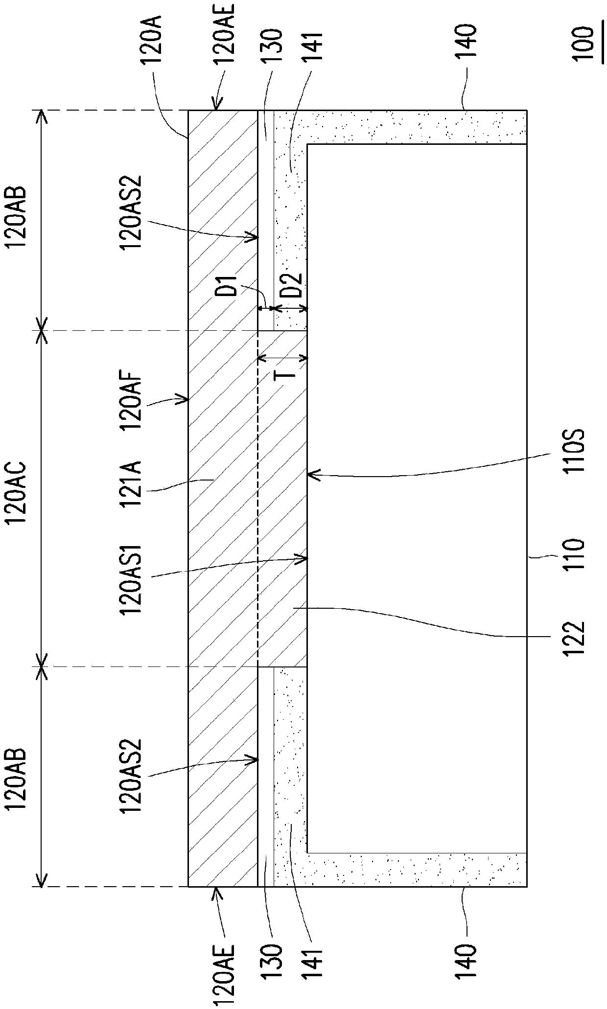
[0053] figure 1 It is a schematic cross-sectional view of a display device according to an embodiment of the present invention. Please refer to figure 1 , a display device 100 of this embodiment includes a display module 110 , a cover plate 120A, an adhesive layer 130 and a frame 140 . The cover plate 120A is disposed on the display module 110 , the frame 140 surrounds the display module 110 and the cover plate 120A is attached to the frame 140 through the adhesive layer 130 .

[0054] The cover plate 120A has a central region 120AC and a peripheral region 120AB. The peripheral area 120AB is located on at least one side of the central area 120AC, wherein figure 1 From the perspective, ...


PUM


Abstract

The invention discloses a display device which comprises a display module and a cover plate. The cover plate is arranged on the display module and provided with a central area and a peripheral area, and the peripheral area is located on at least one side of the central area. The cover plate further comprises a main body part and a protruding part. The main body portion continuously extends into the central region and the peripheral region. The protruding part is arranged in the central area and located between the main body part and the display module, and the protruding part enables the lowersurface of the cover plate in the central area to be closer to the height of the upper surface of the display module relative to the lower surface of the cover plate in the peripheral area. The display device provided by the embodiment of the invention can avoid the problem of picture taste caused by mouth-shaped lamination, and is more economical than comprehensive lamination.

Description

technical field [0001] The present invention relates to a display device, and in particular to a display device with a cover plate. Background technique [0002] In current display devices, a protective cover is pasted on the display module to protect the display module. Cover bonding technology can be mainly divided into air bonding and direct bonding. The letter-shaped bonding is to use a letter-shaped adhesive layer to attach the protective cover to the casing. This method has the advantages of simple manufacturing process and low cost, but there is an air gap between the protective cover and the display module. In this way, due to the refraction phenomenon caused by the light traveling between different media, ghost images are formed, which seriously affects the quality of the picture. Full bonding is to fill the gap between the protective cover and the display module with optical clear adhesive (OCA) or optical clear resin (OCR) to achieve the bonding between the two....

Claims


Application Information

Patent Timeline
Patent Type & Authority Applications(China)
IPC IPC(8): G06F3/041G02F1/1333
CPCG02F1/13338G06F3/0412G02F1/133308G02F2202/28G06F3/041G06F3/044G02F1/133331G02F1/133504G06F1/1601G06F2203/04107
Inventor 邱楷文周芳毅
Owner CHUNGHWA PICTURE TUBES LTD
Learn More