Special tool for orthopaedic medical internal and external fixation instruments

A technology for special tools and instruments, which is applied in the field of special tools for orthopedic medical internal and external fixation instruments, which can solve problems such as insufficient flexibility and troublesome operations, and achieve the effects of convenient use, firm fixation, and large contact area

Inactive Publication Date: 2019-04-26
王复超
View PDF7 Cites 5 Cited by
  • Summary
  • Abstract
  • Description
  • Claims
  • Application Information

AI Technical Summary

Problems solved by technology

[0004] However, during the operation, the position cannot be fixed in one place all the time. Therefore, in the above-mentioned patent, the flexibility is not enough in the actual use process, which brings troubles to the operation.

Method used


Image

  • Special tool for orthopaedic medical internal and external fixation instruments
  • Special tool for orthopaedic medical internal and external fixation instruments
  • Special tool for orthopaedic medical internal and external fixation instruments

Examples


Embodiment 1

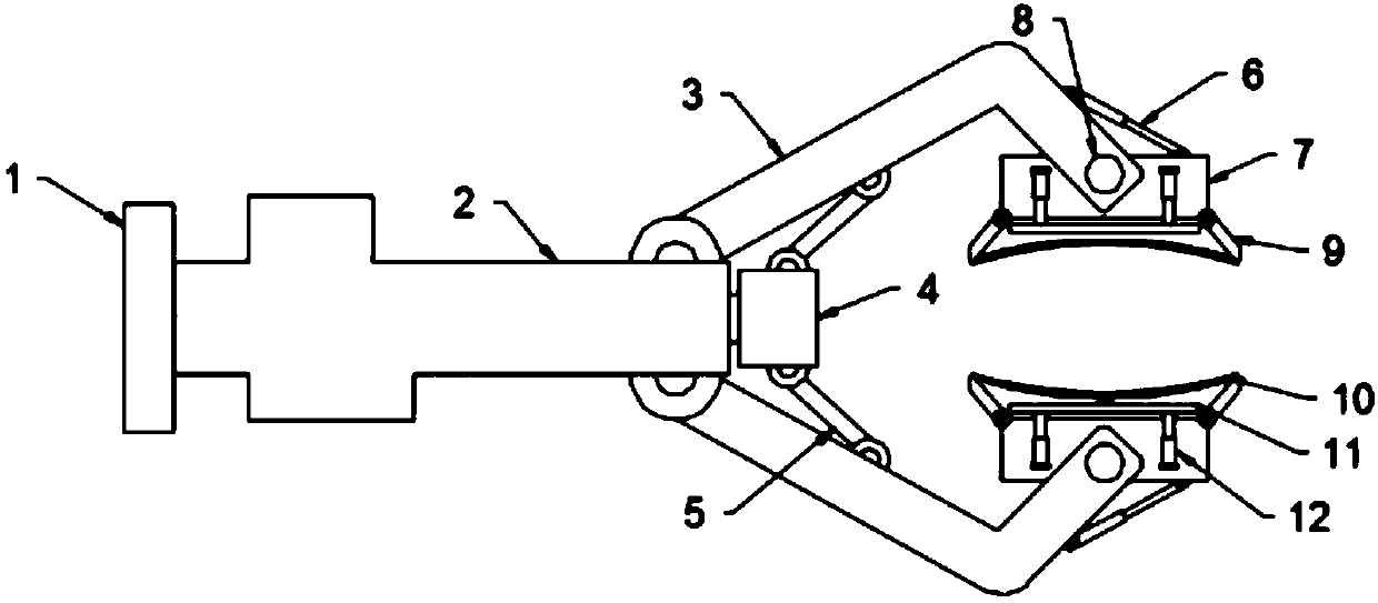
[0029] see Figure 1~3 , in an embodiment of the present invention, a special tool for orthopedic medical internal and external fixation equipment includes a base 1, a fixing sleeve 2, an L-shaped jaw 3 and a clamping block 7; one end of the fixing sleeve 2 is fixed on the base 1 The other end is hinged with one end of the symmetrically arranged L-shaped jaw 3, and the other end of the L-shaped jaw 3 is rotatably connected to the clamping block 7 through the pin shaft 8, and the upper end of the clamping block 7 is connected by the first electric telescopic The rod 6 is hinged with the outer end of the L-shaped jaw 3, and the clamping block 7 can be driven to adjust the angle through the first electric telescopic rod 6 provided, thereby improving the angle adjustment of the medical staff during the operation and being easy to use.

[0030] The side of the clamping block 7 away from the first electric telescopic rod 6 is symmetrically equipped with a movable plate 9, and one en...

Embodiment 2

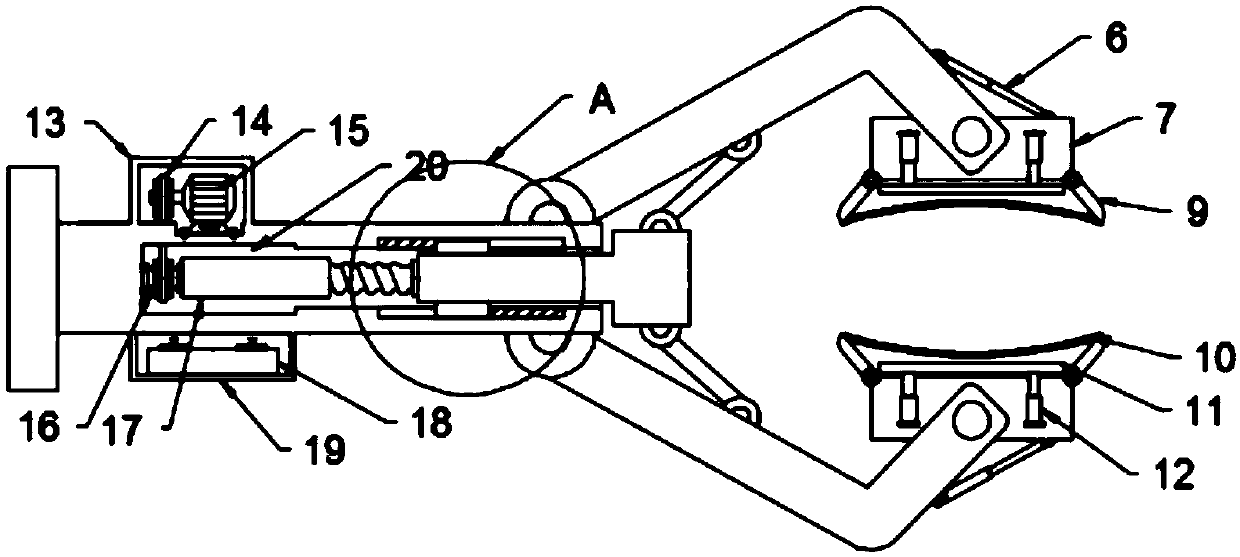
[0038] see Figure 1~5 , in an embodiment of the present invention, a special tool for orthopedic medical internal and external fixation equipment includes a base 1, a fixing sleeve 2, an L-shaped jaw 3 and a clamping block 7; one end of the fixing sleeve 2 is fixed on the base 1 The other end is hinged with one end of the symmetrically arranged L-shaped jaw 3, and the other end of the L-shaped jaw 3 is rotatably connected to the clamping block 7 through the pin shaft 8, and the upper end of the clamping block 7 is connected by the first electric telescopic The rod 6 is hinged with the outer end of the L-shaped jaw 3, and the clamping block 7 can be driven to adjust the angle through the first electric telescopic rod 6 provided, thereby improving the angle adjustment of the medical staff during the operation and being convenient to use.

[0039]The side of the clamping block 7 away from the first electric telescopic rod 6 is symmetrically equipped with a movable plate 9, and o...


PUM


Abstract

The invention discloses a special tool for orthopaedic medical internal and external fixation instruments. The special tool comprises a base, a fixed sleeve, an L-shaped clamping claw and a clamping block, wherein one end of the fixed sleeve is fixedly arranged on the base, and the other end of the fixed sleeve is hinged to one end of the symmetrical L-shaped clamping claw; the other end of the L-shaped clamping claw is rotatably connected with the clamping block through a pin roll; the upper end of the clamping block is hinged to the outer side end of the L-shaped clamping claw through a first electric telescopic pole; one side, away from the first electric pole, of the clamping block is symmetrically provided with movable plates; certain ends of the two movable plates are hinged to the clamping block; the other ends of the two movable plates are connected with a rubber cushion; a resisting plate is arranged between the two movable plates; and the resisting plate is connected with a resisting plate through a second electric telescopic pole at the inner side of the clamping block. The special tool adopts a novel design, and can drive the clamping block to perform angle regulation through the first electric telescopic pole, so that angle regulation is improved when a medical worker performs operation, and the use is convenient.

Description

technical field [0001] The invention relates to the technical field of medical devices, in particular to a special tool for orthopedic medical internal and external fixation devices. Background technique [0002] The department is one of the most common departments in major hospitals. It mainly studies the anatomy, physiology and pathology of the musculoskeletal system, and uses drugs, surgery and physical methods to maintain and develop the normal shape and function of this system. When drilling bone holes, when using a drill jig to fix the electric drill, it is very troublesome to install and disassemble due to design reasons, and it is easy to loosen during use. It reduces the operational difficulty of medical personnel. [0003] The existing Chinese patent CN 108078608 A discloses a special tool for orthopedic medical internal and external fixation devices, including a mounting plate, the mounting plate is arranged in two Z-shaped symmetrical structures, and the bottom ...

Claims


Application Information

Patent Timeline
Patent Type & Authority Applications(China)
IPC IPC(8): A61B17/17
CPCA61B17/17
Inventor 王复超刘玉荣
Owner 王复超
Why Eureka
Try Eureka