Appearance identification and model mistake-proofing mechanism of factory processing line

A processing line and appearance technology, which is applied in the field of appearance identification and model error prevention mechanism of factory processing line, can solve the problems of low detection efficiency, slow observation speed, low customer satisfaction, etc., to increase the pass rate and increase stability , the effect of improving quality

Inactive Publication Date: 2021-03-09
上海诚延自动化技术有限公司
View PDF0 Cites 0 Cited by
  • Summary
  • Abstract
  • Description
  • Claims
  • Application Information

AI Technical Summary

Problems solved by technology

[0004] In view of the above situation, in order to overcome the defects of the prior art, the present invention provides an appearance identification and model error prevention mechanism of the factory processing line, which effectively solves the problem that the existing factory processing line often uses workers to process The finished raw materials are inspected and packaged, but the workers are often fatigued or the observation speed is slow when inspecting, resulting in low detection efficiency and low customer satisfaction in later sales

Method used


Image

  • Appearance identification and model mistake-proofing mechanism of factory processing line
  • Appearance identification and model mistake-proofing mechanism of factory processing line
  • Appearance identification and model mistake-proofing mechanism of factory processing line

Examples


Embodiment 1

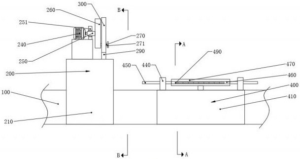
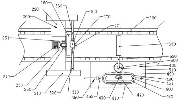
[0028] Embodiment one, by figure 1 , figure 2 , image 3 , Figure 4 , Figure 5 and Figure 6Given, the present invention includes a conveying device 100, an adjusting device 200 is fixedly installed on the upper part of the conveying device 100, and the adjusting device 200 includes two groups of first support plates 210, second support plates 220, first support blocks 230, first motors 240, The first rotating rod 250, the disc 260, the adjusting rod 270, the second rotating rod 280, the connecting plate 290, the first return plate 300, the first sector gear 310, the guide rod 320 and the tooth plate 330, the first two groups The supporting plates 210 are respectively located on the front and rear sides of the conveying device 100, the front and rear ends of the second supporting plate 220 are respectively connected to the tops of the two sets of first supporting plates 210 on the opposite side, and the first supporting block 230 is fixedly installed on the second suppo...

Embodiment 2

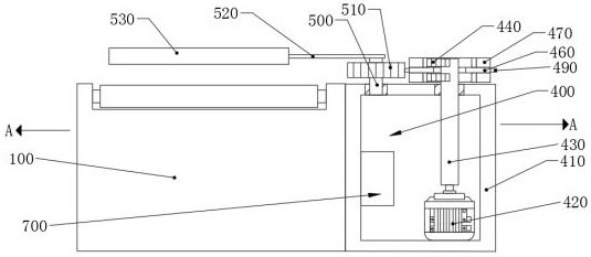
[0029] Embodiment two, on the basis of embodiment one, by image 3 Given, the screening device 400 includes a placement box 410, a third motor 420, a fourth rotating rod 430, two sets of second sector gears 440, a second return-shaped plate 460, two sets of third return-shaped plates 470, multiple sets of first Teeth 480, multiple sets of second teeth 490, fifth rotating rod 500, first gear 510, connecting rod 520, anti-collision sleeve 530, storage box 410 are fixedly installed on the front end of the transmission device 100, and the third motor 420 is fixedly installed In the inner cavity of the placement box 410, the bottom ends of the fourth rotating rods 430 are fixedly installed on the transmission shaft of the third motor 420, and the bottom ends of the two groups of fourth rotating rods 430 penetrate the top wall of the placement case 410 and connect with the two groups of second rotating rods. The sector gears 440 are connected, and the second return-shaped plates 460...

Embodiment 3

[0031] Embodiment three, on the basis of embodiment one, by Figure 4 Given, the rotating device 340 includes an action box 341, a second motor 342 and a third rotating rod 343, the top of the action box 341 is connected to the bottom end of the tooth plate 330, and the second motor 342 is fixedly installed in the inner cavity of the action box 341 The top wall of the top wall of the third rotating rod 343 is connected with the transmission end of the second motor 342, and the bottom end of the third rotating rod 343 runs through the bottom wall of the action box 341 and is connected with the top of the laser scanning probe 600.

[0032] By setting the rotating device 340, the angle adjustment of the device to the laser scanning probe 600 can be increased, so that after the raw material passes through the lower side of the laser scanning probe 600, the rear side of the raw material can be detected.


PUM


Abstract

The invention relates to the technical field of processing lines, and discloses an appearance identification and model mistake-proofing mechanism of a factory processing line. The appearance identification and model mistake-proofing mechanism of the factory processing line comprises a conveying device, an adjusting device is fixedly installed on the upper portion of the conveying device, the adjusting device comprises two sets of first supporting plates, a second supporting plate, a first supporting block and a first motor. According to the novel scheme, through the arrangement of the adjusting device, the position of a laser scanning probe can be adjusted, and therefore the laser scanning probe can carry out detection on raw materials at different angles, the detection efficiency and efficacy are improved; through the arrangement of a rotating device, the angle adjustment of the appearance identification and model mistake-proofing mechanism on the laser scanning probe can be increased, and therefore after the raw materials pass through the lower side of the laser scanning probe, detection can be carried out on the rear sides of the raw materials; and through the arrangement of a screening device, defective products in the raw materials can be removed, the product quality is improved, the percent of pass of warehouse-out products of a factory is increased, meanwhile, the removed raw materials can be reutilized, and the situation that the defective raw materials are inconvenient to recycle in the later period is avoided.

Description

technical field [0001] The invention belongs to the technical field of processing lines, in particular to an appearance identification and model error prevention mechanism of a factory processing line. Background technique [0002] Modern manufacturing plants and production enterprises are also called factories. They are large-scale industrial buildings used to produce goods. Most factories have production lines composed of large machines or equipment. In the modern history of the world, they generally refer to the large-scale production of capitalist machines. , that is, capitalist industrial sites where manual labor is replaced by mechanized labor. [0003] The existing factory processing line often uses workers to inspect and package the processed raw materials when performing assembly line operations. However, workers are often fatigued or slow to observe during inspection, resulting in relatively low detection efficiency. Among them, customer satisfaction is low. There...

Claims


Application Information

Patent Timeline
Patent Type & Authority Applications(China)
IPC IPC(8): B07C5/00B07C5/342B07C5/10B07C5/36
CPCB07C5/00B07C5/10B07C5/342B07C5/361B07C5/362
Inventor 项双良
Owner 上海诚延自动化技术有限公司
Why Eureka
Try Eureka