No-stamping punching mold

A stamping die and stamping technology, applied in forming tools, manufacturing tools, metal processing equipment, etc., can solve the problems of increasing die cost, time-consuming, complicated operation, etc., and achieve balanced support force, convenient replacement and convenient cost. Effect

Inactive Publication Date: 2019-04-26
SUZHOU BAIDA PRECISION MACHINERY
View PDF6 Cites 0 Cited by
  • Summary
  • Abstract
  • Description
  • Claims
  • Application Information

AI Technical Summary

Problems solved by technology

In the lower mold of the stamping die, there is an inserting part, which is connected to the lower template through a hanging table. If the inserting part is damaged, the entire lower die structure needs to be dismantled. The replacement process is cumbersome and takes a long time, which greatly increases cost of mold development

Method used


Image

  • No-stamping punching mold

Examples


Embodiment Construction

[0011] The present invention will be further described below in conjunction with accompanying drawing.

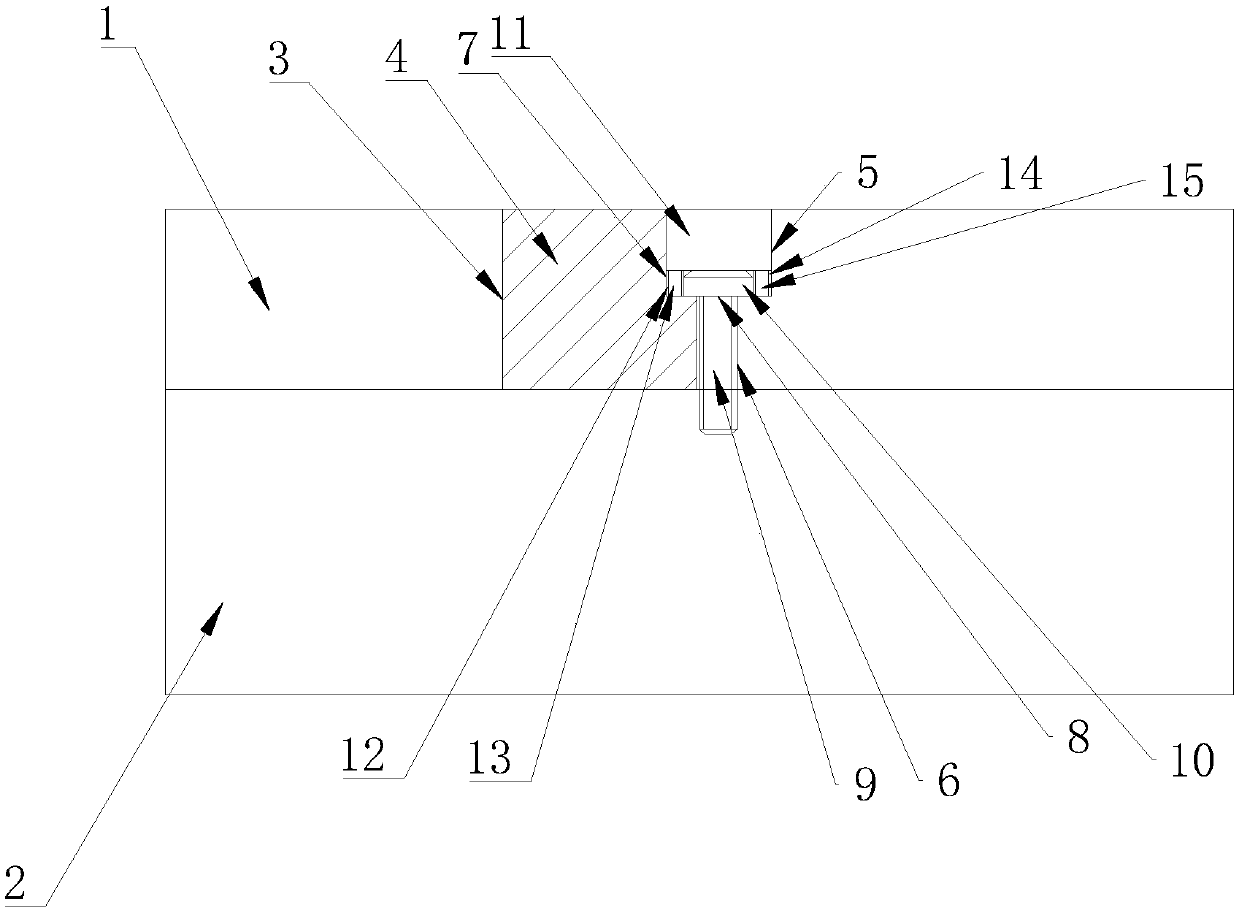
[0012] Such as figure 1 As shown, a stamping die without stamping includes a lower template 1 and a lower cushion block 2 arranged below the lower template 1, and the lower template 1 is provided with a placement groove 3 for placing an entry block 4, and the placement groove 3 One side of the mounting groove 5 is communicated with a mounting groove 5, and a bolt hole 6 is arranged in the mounting groove 5. The bolt hole 6 penetrates the lower formwork 1 and extends into the lower pad 2. One side is provided with a fixing groove 7, the bolt hole 6 is provided with a hexagonal bolt 8, the lower template 1 and the lower pad 2 are fixedly connected by the hexagonal bolt 8, and the hexagonal bolt 8 includes a threaded column 9 and a head 10 , the head 10 abuts against the bottom of the fixing groove 7, a first magnet assembly is arranged between the side wall of the fixing gro...


PUM


Abstract

The invention discloses a no-stamping punching mold. The no-stamping punching mold is characterized in that a lower template is provided with a placing groove for placing a block; one side of the placing groove communicates with a mounting groove; a bolt hole is formed in the mounting groove; the bolt hole penetrates through the lower template, and extends into a lower cushion block; a fixed groove is formed in the side, towards the bolt hole, of the block; a hexagonal bolt is arranged in the bolt hole, and comprises a thread column and a head part; the head part butts against the bottom of the fixed groove; a first magnet module is arranged between the side wall of the fixed groove and the head part; a second magnet module is arranged between the side wall of the mounting groove and the head part; filling iron blocks butting against and attracting with the first magnet and the second magnet are arranged in the placing groove and the mounting groove; the tops of the filling iron blocksare leveled with the surface of the lower template; and the filling iron blocks and the block are bonded with the inner wall of the lower template. The no-stamping punching mold is convenient to disassemble and replace, free of stamping and low in cost.

Description

technical field [0001] The invention relates to the technical field of stamping dies, in particular to a stamping die without stamping. Background technique [0002] The stamping die is to use the powerful stamping of the stamping die to realize the stamping process of the product. In the lower mold of the stamping die, there is an inserting part, which is connected to the lower template through a hanging table. If the inserting part is damaged, the entire lower die structure needs to be dismantled. The replacement process is cumbersome and takes a long time, which greatly increases The cost of mold development is reduced. Contents of the invention [0003] In view of the deficiencies in the prior art, the main purpose of the present invention is to provide a stamping die without stamping that is easy to disassemble and replace without stamping and has a stable structure. [0004] In order to achieve the above object, the present invention provides the following technica...

Claims


Application Information

Patent Timeline
Patent Type & Authority Applications(China)
IPC IPC(8): B21D37/10B21D37/04
CPCB21D37/04B21D37/10
Inventor 丁飞
Owner SUZHOU BAIDA PRECISION MACHINERY
Why Eureka
Try Eureka