Pneumatic rear clamping disc for pipe cutting machine

A technology of pipe cutting machine and chuck, which is applied in the direction of chuck, etc., can solve the problems of poor alignment and inability to save tailings, etc., and achieve the effects of easy operation, expanding the range of clamping, and improving the accuracy of clamping

Pending Publication Date: 2019-04-26
SHANDONG LEIMING CNC LASER EQUIP CO LTD
View PDF2 Cites 2 Cited by
  • Summary
  • Abstract
  • Description
  • Claims
  • Application Information

AI Technical Summary

Problems solved by technology

[0004] The purpose of the present invention is to solve the above-mentioned problems in the prior art, and provide a pneumatic rear chuck for a pipe cutting machine, which uses a cylinder to simultaneously drive the first jaw unit and the second jaw unit, so that the rear chuck can move flexibly , easy to operate, and the simple mechanical structure and independent air circuit design make the structure of the rear chuck more compact and the clamping more reliable. Disadvantages such as the chuck passes through the front chuck cavity to save tailings, etc.

Method used


Image

  • Pneumatic rear clamping disc for pipe cutting machine
  • Pneumatic rear clamping disc for pipe cutting machine
  • Pneumatic rear clamping disc for pipe cutting machine

Examples


Embodiment Construction

[0033] Below in conjunction with accompanying drawing, the present invention is described in further detail:

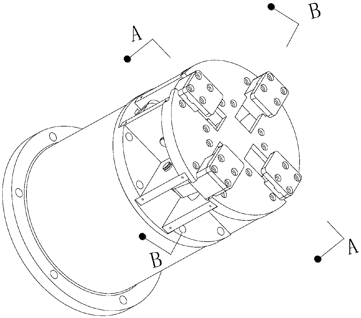
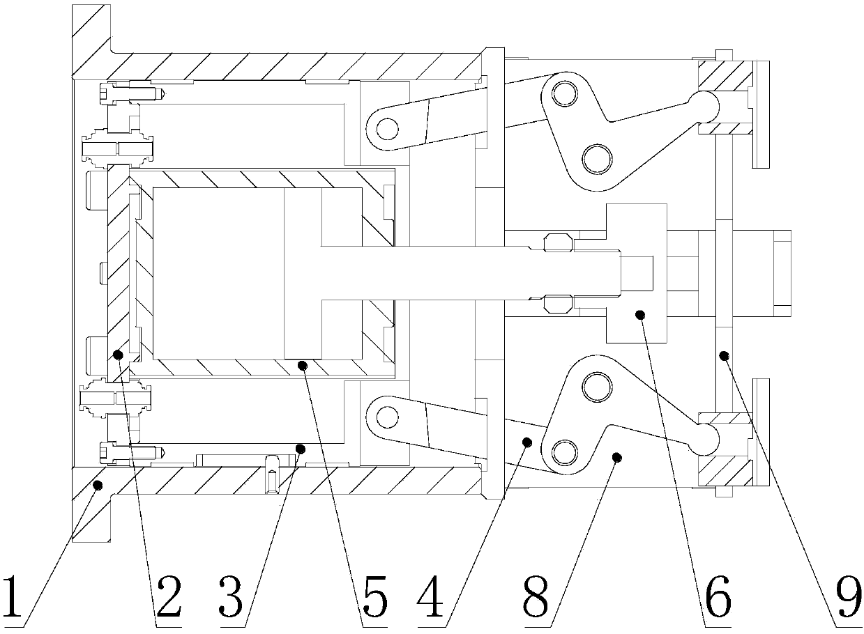
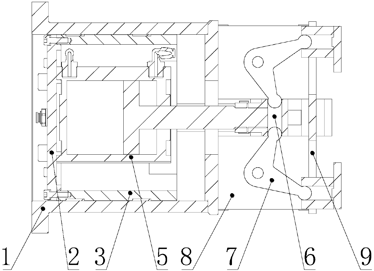
[0034] Such as Figure 1-4 As shown, a pneumatic rear chuck for a pipe cutting machine includes a fixed seat 1, a piston 3, a cylinder 5, a fixed frame 8, a push block 6, a first jaw unit 4 and a second jaw unit 7, the fixed The top of seat 1 is provided with fixed frame 8, and the top of described fixed frame 8 is provided with end plate 9, and described fixed seat 1 is provided with piston 3, and the inside of described piston 3 is fixed with cylinder 5, and the inside of described cylinder 5 The push rod passes through the fixed frame 8, the end of the push rod is provided with a push block 6, and the first claw unit 4 and the second claw unit 7 are arranged symmetrically on the end plate 9, and the first claw unit 4 and the second claw unit 7 are arranged symmetrically. The claw unit 4 is connected with the piston 3 , and the second claw unit 7 is connected with ...


PUM


Abstract

The invention provides a pneumatic rear clamping disc for a pipe cutting machine. The pneumatic rear clamping disc comprises a fixing base, a piston, an air cylinder, a fixing frame, a pushing block,a first clamping claw unit and a second clamping claw unit. The fixing frame is arranged on the top of the fixing base. An end plate is arranged on the top of the fixing frame. The piston is arrangedin the fixing base. The air cylinder is fixed in the piston. A pushing rod of the air cylinder penetrates through the fixing frame. The pushing block is arranged at the tail end of the pushing rod. The first clamping claw unit and the second clamping claw unit are symmetrically arranged on the end plate. The first clamping claw unit is connected with the piston. The second clamping claw unit is connected with the pushing block. According to the pneumatic rear clamping disc, the same air cylinder is adopted for driving the first clamping claw unit and the second clamping claw unit at the same time, the rear clamping disc is flexible in motion and easy to operate, meanwhile, by means of the simple mechanical structure and independent gas circuit design, the rear clamping disc is more compactin construction, clamping is more reliable, and the defects that due to the complex and large structure of the rear clamping disc, operation is troublesome, centering performance is poor, the rear clamping disc cannot penetrate through a cavity of a front clamping disc, and tail materials cannot be saved can be avoided.

Description

technical field [0001] The invention belongs to the technical field of machine tool fixtures, and in particular relates to a pneumatic rear chuck for a pipe cutting machine. Background technique [0002] Pneumatic chuck is one of the more commonly used chucks. It can be centered automatically and has high work efficiency when clamping workpieces. On existing pipe cutting machines, pneumatic chucks are often used for clamping. Pipe cutting machines usually use a pair of front and rear The chuck is used to clamp the material, the rear chuck plays the role of clamping, supporting, and forward feeding, and the front chuck is set in such a way that the pipe material can pass through the front chuck in order to save tailings. This clamping method The designed pneumatic chuck has a compact structure and saves tailings. [0003] However, the action of the existing rear chuck is inflexible and difficult to operate, and the structure of the rear chuck is not compact enough and the cl...

Claims


Application Information

Patent Timeline
Patent Type & Authority Applications(China)
IPC IPC(8): B23B31/16B23B31/24
CPCB23B31/16287
Inventor 赵辉李峰西索海生
Owner SHANDONG LEIMING CNC LASER EQUIP CO LTD
Why Eureka
Try Eureka