A pressure release mechanism and a vacuum adsorption and dust collection device with the pressure release mechanism

A technology of pressure relief and vacuum pipelines, applied in the direction of manufacturing tools, maintenance and safety accessories, metal processing machinery parts, etc., to achieve the effect of high-efficiency long-term operation

Active Publication Date: 2021-01-15
HANS CNC SCI & TECH
View PDF8 Cites 0 Cited by
  • Summary
  • Abstract
  • Description
  • Claims
  • Application Information

AI Technical Summary

Problems solved by technology

[0004] The technical problem to be solved by the present invention is to provide a pressure relief mechanism for the deficiencies of the prior art to overcome the instability of the high-pressure blower due to the inability to ensure that the equipment is always in non-overload operation in the non-processing state in the prior art. Efficient long run

Method used


Image

  • A pressure release mechanism and a vacuum adsorption and dust collection device with the pressure release mechanism
  • A pressure release mechanism and a vacuum adsorption and dust collection device with the pressure release mechanism
  • A pressure release mechanism and a vacuum adsorption and dust collection device with the pressure release mechanism

Examples


Embodiment 1

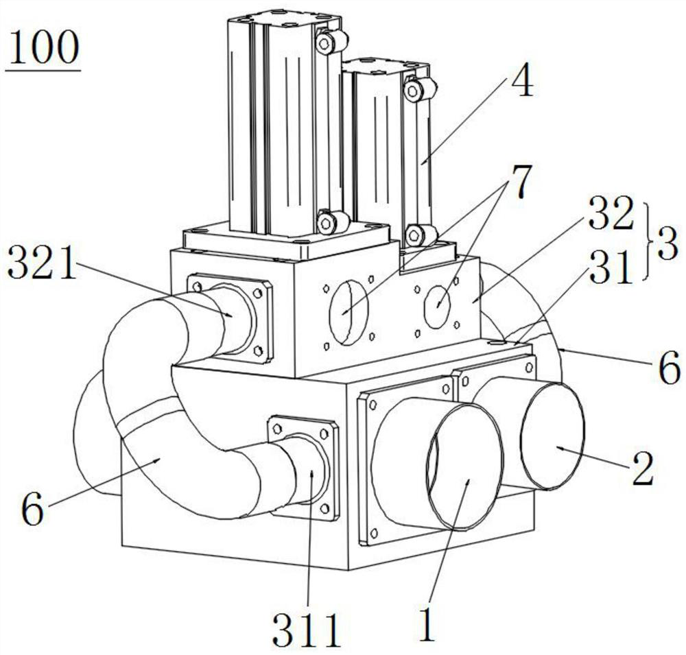
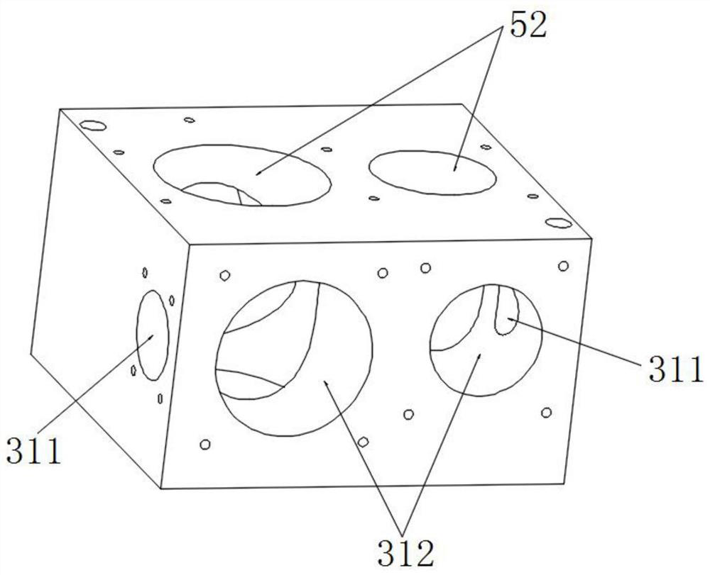
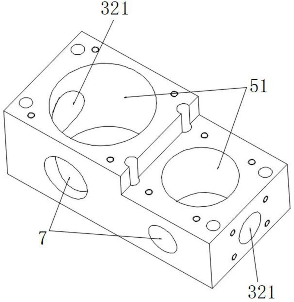
[0027] Such as figure 1 As shown, the pressure relief mechanism 100 in this embodiment includes: a vacuum pipeline 1, a dust suction pipeline 2, and an air distribution block 3. Gas mechanism 4 is located on the gas distribution block 3 and is used to export the negative pressure in the vacuum pipe and the dust suction pipe 6. The gas distribution block 3 is longitudinally provided with a gas distribution mechanism channel, and the vacuum pipe 1 and the dust suction pipe 2 traverse through the channel of the air distribution mechanism and pass through the air distribution block 3. The air distribution block 3 is provided with a pressure relief inlet 7 for allowing air to enter the channel of the air distribution mechanism. By setting the pressure relief pipe 6 for leading out the negative pressure in the vacuum pipeline 1 and the dust suction pipeline 2 and the pressure relief air inlet 7 for allowing air to enter the passage of the air distribution mechanism on the air distri...

Embodiment 2

[0038] Such as Figure 8 As shown, the vacuum adsorption and dust collection device described in this embodiment includes a pressure relief mechanism 100 as described in Embodiment 1, and a high-pressure blower 8; the high-pressure blower 8 has a high-pressure blower suction pipe 9, and the high-pressure blower One end of the suction pipe is connected with the high-pressure blower 8 , and the other end is connected with the pressure relief mechanism 100 . Further, the suction pipe of the high-pressure fan communicates with the pressure relief mechanism 100 through the vacuum pipe 1 and the dust suction pipe 2 .

[0039] Further, when the laser processing equipment is in the non-processing state, the blocking member 41 divides the blocking area of ​​the vacuum pipeline 1 and the dust suction pipeline 2 into two parts. The first vacuum pipeline 11 connected with 9 and the second vacuum pipeline 12 arranged oppositely, the dust suction pipeline 2 includes the first dust suction ...


PUM


Abstract

The invention relates to a pressure-relieving mechanism and a vacuum adsorption and dust collection device provided with the same. The pressure-relieving mechanism comprises a vacuum pipeline, a suction collection pipeline, an air separating block, an air separating mechanism arranged on the air separating block for controlling on-off of the vacuum pipeline and the dust collection pipeline and a pressure-relieving pipe arranged on the air separating block for exporting negative pressures in the vacuum pipeline and the dust collection pipeline. An air separating mechanism channel is verticallyarranged on the air separating block, the vacuum pipeline and the dust collection pipeline penetrate the air separating mechanism channel transversely and are arranged on the air separating block in apenetrating manner, and a pressure-relieving air inlet through which air enters the air separating mechanism channel is formed in the air separating block. By arranging the pressure-relieving pipe and the pressure-relieving air inlet in the air separating block, a pressure-relieving channel formed by the pressure-relieving air inlet and the pressure-relieving pipe can be connected to a suction pipeline of a high pressure fan effectively. When laser processing equipment is in a non-processed state, the negative pressure in the air separating mechanism channel can be released immediately, so that the machine is still in non-overload work, and the high pressure fan operates stably and efficiently for a long time.

Description

technical field [0001] The invention relates to the technical field of laser processing and production, in particular to a pressure relief mechanism and a vacuum adsorption and dust collection device with the pressure relief mechanism. Background technique [0002] When laser processing flexible boards, two suction pipes branched from the suction port of the high-pressure fan are used to vacuumize the processing platform and vacuum the dust generated by laser processing respectively. During laser processing, laser processing equipment is constantly switched between processing and non-processing, but the high-pressure fan usually works continuously during laser processing, so it is necessary to use a gas distribution component to control the flow of vacuum pipes and dust suction pipes. on and off. [0003] When the laser processing equipment is in the processing and non-processing state, the high-pressure fan will have two states of non-overload and overload. The high-pressu...

Claims


Application Information

Patent Timeline
Patent Type & Authority Patents(China)
IPC IPC(8): B23Q11/00B23K26/70
CPCB23K26/702
Inventor 范建辉覃涛翟学涛杨朝辉高云峰
Owner HANS CNC SCI & TECH
Why Eureka
Try Eureka