
Metal carbon tube component for purifying wastewater and electrocatalytic oxidation device

A technology of electrocatalytic oxidation and metal components, applied in the direction of oxidized water/sewage treatment, water/sewage treatment, chemical instruments and methods, etc., can solve the problem of high cost of treatment equipment investment, depreciation and maintenance, complex treatment process, and small treatment capacity and other problems, to achieve the effect of long-term stable and effective operation, improved reaction efficiency, and fast response speed

Active Publication Date: 2012-09-19
深圳市地大东江环境研究院
View PDF3 Cites 7 Cited by
  • Summary
  • Abstract
  • Description
  • Claims
  • Application Information

AI Technical Summary

Problems solved by technology

For the evaporation treatment of the concentrated liquid, foreign countries currently use multi-stage (generally above 4-stage evaporators, and the condensed water still needs to be reprocessed to ensure that the COD of the effluent is less than 100mg / l, and the cost of evaporation treatment is currently no lower than 200 yuan / ton
[0010] Landfill leachate NF and RO membrane concentrates are a special kind of wastewater. The investment and operating costs of their treatment are much higher than those of general urban industrial wastewater. Complex process
The processing capacity is generally relatively small, resulting in high processing equipment investment, depreciation, maintenance and other costs

Method used


Image

  • Metal carbon tube component for purifying wastewater and electrocatalytic oxidation device
  • Metal carbon tube component for purifying wastewater and electrocatalytic oxidation device
  • Metal carbon tube component for purifying wastewater and electrocatalytic oxidation device

Examples


Embodiment Construction

[0054] The present invention will be described in further detail below in conjunction with the accompanying drawings and embodiments. It should be understood that the specific embodiments described here are only used to explain the present invention, not to limit the present invention.

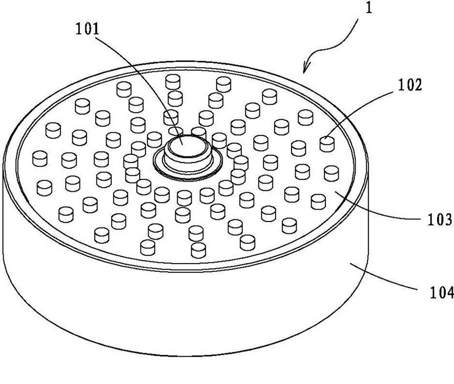
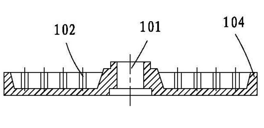
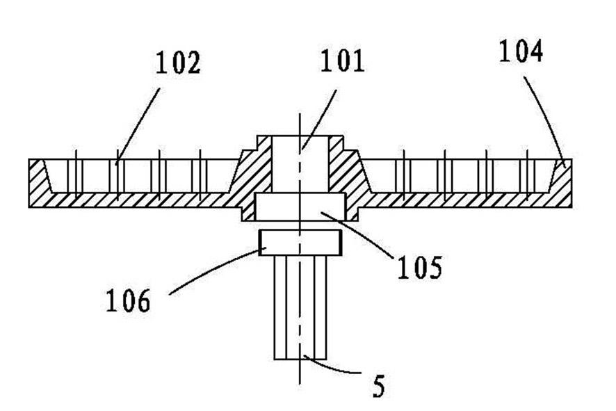
[0055] see Figure 1-Figure 5 , the present invention firstly provides a metal carbon tube assembly 1 for purifying high-concentration organic wastewater such as landfill leachate NF and RO membrane concentrate, which includes a metal disc 104 and at least one center pipe 101, and the center pipe 101 The side wall is provided with a plurality of evenly distributed first through holes (not shown in the figure), and each first through hole is formed during processing and arranged radially along the side wall of the central tube 101 . The central tube 101 is placed in the center of the inner cavity of the metal disc 104 with one end closed, and can be integrally formed with the metal disc 104. A...


PUM


Abstract

The invention provides a metal carbon tube component for purifying wastewater. The metal carbon tube component comprises a metal disk and a central tube which is arranged in the inner cavity of the metal disk, wherein a plurality of first through holes used for making wastewater flow into the metal disk are radially formed in the side wall of the central tube; an electrocatalytic material is filled between the outer wall of the central tube and the inner wall of the metal disk; and a plurality of second through holes are axially formed in the disk surface of the metal disk. Due to a structure of flowing anodes and central water distribution, the metal carbon tube component is provided with a channel with a great specific surface area and uniform water flow and gas flow, so that wastewater treatment has higher current density and better catalytic reaction effect. The invention also provides an electrocatalytic oxidation device. The electrocatalytic oxidation device comprises a plurality of metal carbon tube components which are overlapped. Each component is arranged in the inner cavity of a shell, an anode pipe passes through the central tube; both ends are fixed by a support frame respectively and are closed; and one end of the shell is provided with a water inlet and a gas outlet, and the other end of the shell is provided with a water outlet and a drain outlet. The device integrates multiple functions into a whole, has low treatment cost and a good effect of removing organic pollutants.

Description

【Technical field】 [0001] The invention belongs to the field of wastewater purification, and relates to an electrocatalytic component and an electrocatalytic oxidation device thereof, in particular to a metal carbon tube component and an electrocatalytic oxidation device for purifying high-concentration organic wastewater such as landfill leachate NF and RO membrane concentrate device. 【Background technique】 [0002] With the rapid development of social economy, the industrialization and urbanization of human society are increasing day by day, and the phenomenon of water pollution is becoming more and more serious. In particular, municipal solid waste landfills or landfill leachate from waste-to-energy plants represent high concentrations of organic wastewater. According to the principle of "harmless, reduction, and recycling" of waste disposal in my country, a large number of domestic waste sanitary landfills or waste incineration power plants will be newly built. Whether ...

Claims


Application Information

Patent Timeline
IPC IPC(8): C02F1/461C02F1/72C02F1/78
Inventor 彭云龙刘娟陈兆勇唐伟中
Owner 深圳市地大东江环境研究院
Learn More