
Lock assembly machine and bolt assembly mechanism thereof

A technology of assembly mechanism and assembly device, which is applied in assembly machines, manufacturing tools, metal processing, etc., and can solve the problems of undocumented, standardized lock tongue orientation, etc.

Pending Publication Date: 2019-04-26
张必葵
View PDF0 Cites 5 Cited by
  • Summary
  • Abstract
  • Description
  • Claims
  • Application Information

AI Technical Summary

Problems solved by technology

However, the above-mentioned plan does not record how to regulate the orientation of the lock tongue during the feeding process, because the lock cylinder foot and the lock tongue groove must be hooked when the lock tongue and the lock cylinder are assembled, but the scheme does not explain how to adjust the orientation of the lock tongue are limited, so further optimization is required

Method used


Image

  • Lock assembly machine and bolt assembly mechanism thereof
  • Lock assembly machine and bolt assembly mechanism thereof
  • Lock assembly machine and bolt assembly mechanism thereof

Examples


Embodiment Construction

[0024] Embodiments of the present invention are described in detail below, examples of which are shown in the drawings, wherein the same or similar reference numerals designate the same or similar elements or elements having the same or similar functions throughout. The embodiments described below by referring to the figures are exemplary and are intended to explain the present invention and should not be construed as limiting the present invention.

[0025] In describing the present invention, it should be understood that the terms "center", "longitudinal", "transverse", "length", "width", "thickness", "upper", "lower", "front", " The orientations or positional relationships indicated by "rear", "left", "right", "vertical", "horizontal", "top", "bottom", "inner", "clockwise", "counterclockwise" are based on the attached The orientation or positional relationship shown in the figure is only for the convenience of describing the present invention and simplifying the description...


PUM


Abstract

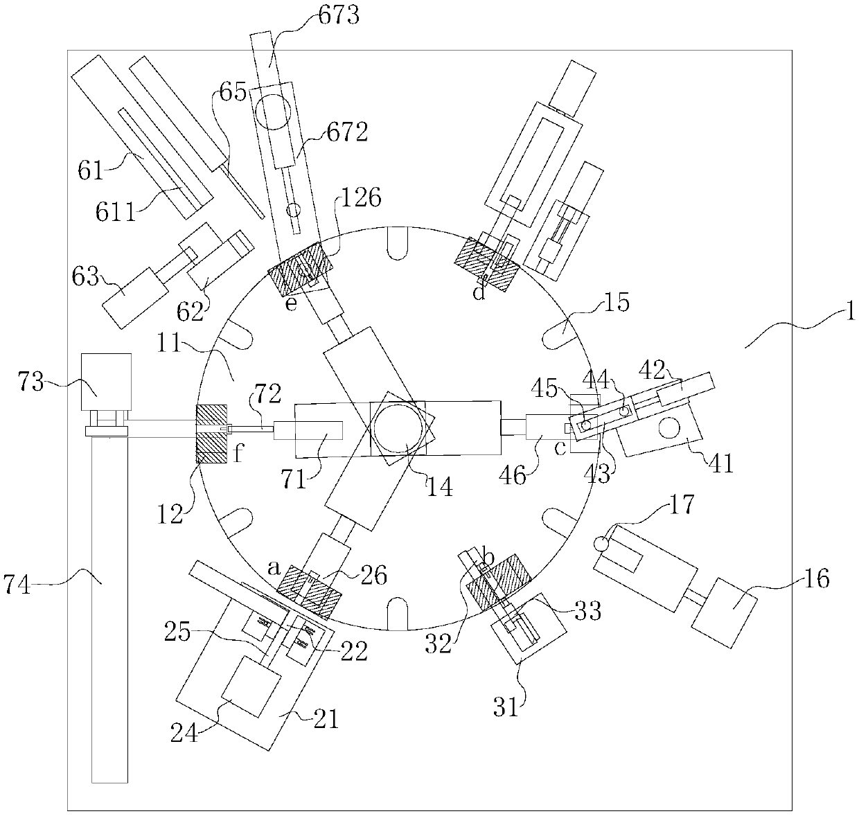
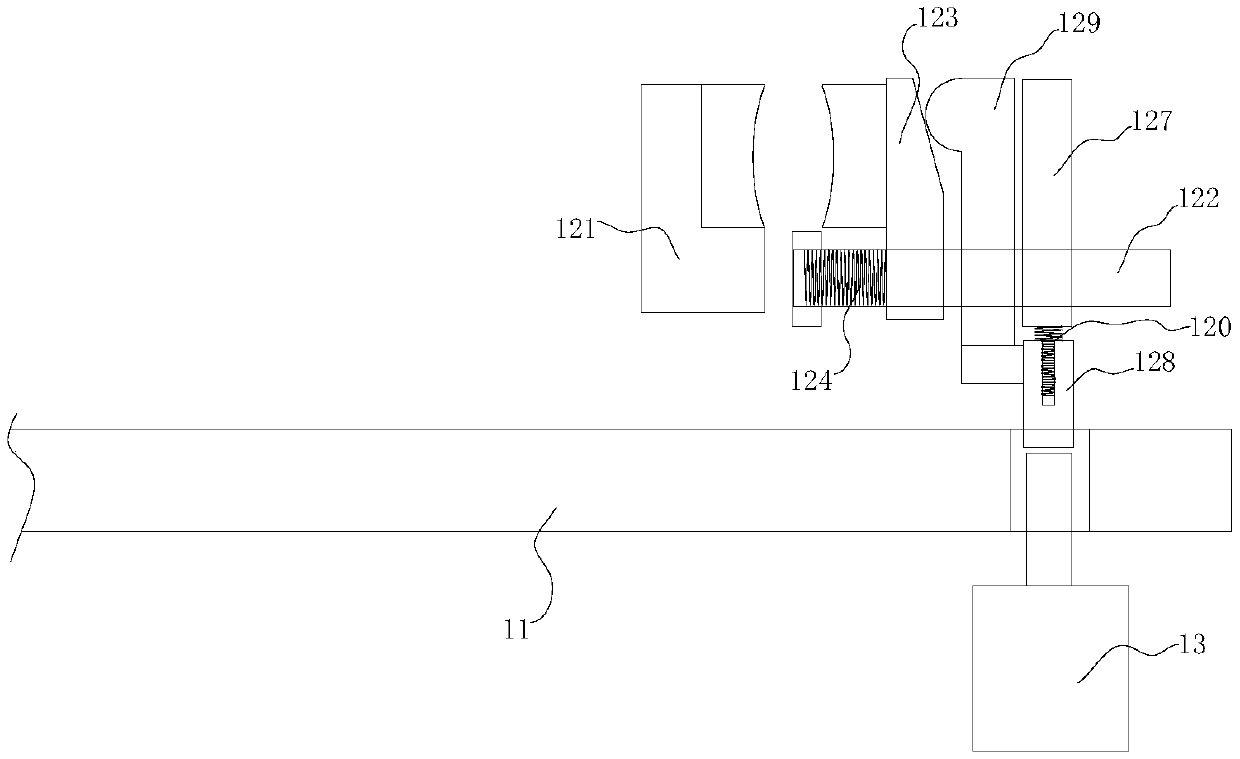
The invention relates to the field of lock assembly. A bolt assembly mechanism comprises a bolt feeding assembly and a bolt assembly device. The bolt feeding assembly comprises a bolt discharge disc,a bolt material pipe, a bolt conveying plate and a bolt feeding air cylinder. A bolt channel is formed in the bolt conveying plate. An elastic blocking piece is arranged at the outlet end of the boltchannel. The bolt channel is divided into a first channel section, a second channel section and a third channel section sequentially between the inlet end to the outlet end. The bolt feeding air cylinder is arranged on the bolt conveying plate. A bolt push component is arranged at the output end of the bolt feeding air cylinder and comprises a fixed plate fixed to the output end of the bolt feeding air cylinder, and a movable push plate hinged to the fixed plate. The movable end of the movable push plate is provided with a sharp part for being clamped into a bolt groove, and the side, close tothe hinged end, of the sharp part is provided with a bevel. The bolt assembly mechanism has the effects that the orientation of a bolt can be standardized, and the bolt is accurately conveyed in andassembled.

Description

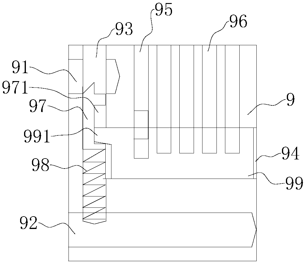
technical field [0001] The invention relates to the field of lock assembly, in particular to a lock assembly machine and a lock bolt assembly mechanism thereof. Background technique [0002] As a traditional lock, the padlock is equipped with a ring-shaped or "one"-shaped metal stalk that can be buckled on the lock body, that is, a "lock beam", so that the padlock is directly buckled with the lock body through the lock beam to form a closed lock. Padlock comprises lock body 9 and lock beam, as figure 1 As shown, lock beam shallow hole 91, lock beam deep hole 92, lock bolt hole 93, lock core hole 94, vertical milling bullet hole 95 and pin hole 96 are provided on the lock body, wherein, lock beam shallow hole 91 is connected with lock core The hole 94 communicates with the deadbolt hole 93, the lock cylinder hole 94 is used to install the lock core, the dead bolt hole 93 is used to install the dead bolt 97 and the dead bolt spring 98, the middle part of the dead bolt is prov...

Claims


Application Information

Patent Timeline
Patent Type & Authority Applications(China)
IPC IPC(8): B23P19/04B23P21/00
CPCB23P19/001B23P19/04B23P21/006
Inventor 张必葵
Owner 张必葵
Learn More