Press ink recovery device

A recycling device and printing machine technology, which is applied in the direction of printing machines, printing, general parts of printing machinery, etc., can solve the problems of low filtration efficiency, achieve high filtration efficiency, short filtration time, and improve the sealing effect

Active Publication Date: 2019-04-26
山东诚丰包装股份有限公司
View PDF8 Cites 4 Cited by
  • Summary
  • Abstract
  • Description
  • Claims
  • Application Information

AI Technical Summary

Problems solved by technology

[0003] The purpose of the present invention is to provide an ink recovery device for printing machines, which has the advantage of high filtration efficiency and solves the problem of low filtration efficiency of common printing machine ink recovery devices

Method used


Image

  • Press ink recovery device
  • Press ink recovery device

Examples


no. 1 approach

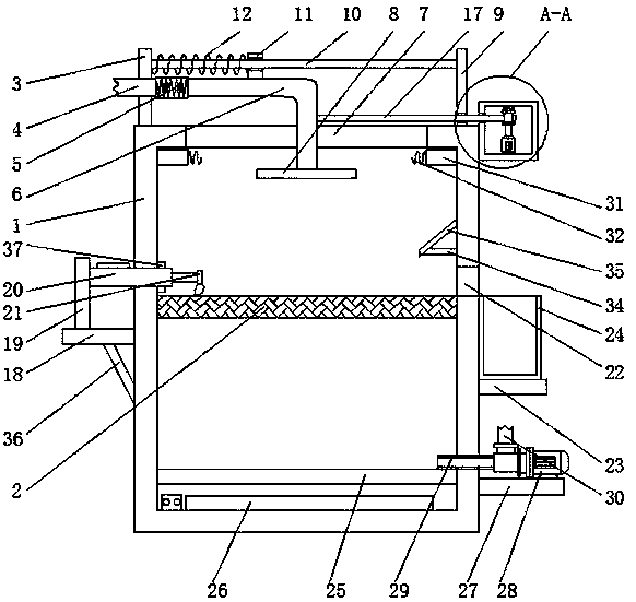
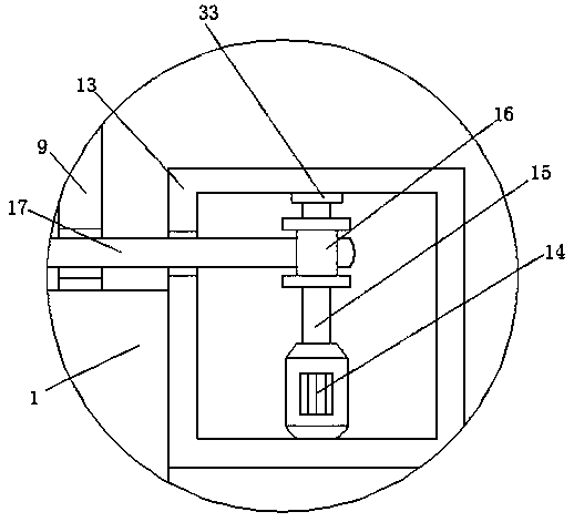
[0017] First implementation: see Figure 1-2, an ink recovery device for a printing machine, comprising a housing 1, a filter screen 2 is fixedly connected to the inner wall of the housing 1, a support block 3 is fixedly connected to the left side of the top of the housing 1, and the left side of the support block 3 is provided with a second An oil outlet pipe 4, the right end of the first oil outlet pipe 4 runs through the support block 3 and extends to its right side, the surface of the first oil outlet pipe 4 is fixedly connected with the inner wall of the support block 3, and the right end of the first oil outlet pipe 4 is sleeved with a telescopic The right end of the pipe 5 and the telescopic pipe 5 is sleeved with a second oil outlet pipe 6, and the top of the casing 1 is provided with a first through groove 7, and the end of the second oil outlet pipe 6 away from the telescopic pipe 5 runs through the first through groove 7 and the shell in turn. The body 1 extends to ...

no. 2 approach

[0020] The second embodiment: as shown in claim 1, an ink recovery device for a printing machine includes a housing 1, a filter screen 2 is fixedly connected to the inner wall of the housing 1, and the left side of the top of the housing 1 A support block 3 is fixedly connected, the left side of the support block 3 is provided with a first oil outlet pipe 4, the right end of the first oil outlet pipe 4 passes through the support block 3 and extends to the right side thereof, the first oil outlet pipe 4 The surface of the support block 3 is fixedly connected to the inner wall of the support block 3, the right end of the first oil outlet pipe 4 is sleeved with a telescopic tube 5, the right end of the telescopic tube 5 is sleeved with a second oil outlet pipe 6, and the top of the housing 1 A first through groove 7 is opened, and the end of the second oil outlet pipe 6 away from the telescopic pipe 5 passes through the first through groove 7 and the casing 1 in turn and extends t...


PUM


Abstract

The invention discloses a press ink recovery device comprising a shell. A strainer is fixedly connected to the inner wall of the shell. A support block is fixedly connected to the left side of the topof the shell. A first oil outlet pipe is arranged on the left side of the support block. The right end of the first oil outlet pipe penetrates through the support block and extends to the right sideof the support block. The surface of the first oil outlet pipe is fixedly connected to the inner wall of the support block. The right end of the first oil outlet pipe is sleeved with a telescopic pipe. The right end of the telescopic pipe is connected with a second oil outlet pipe in a sleeving mode. Through mutual matching of a slider, a sliding block, a buffer spring, a rotary motor, a rotary shaft, a reel, a fixed rope, an electric push rod, a brush, a second through groove and a waste box, the effect of high filtration efficiency is achieved, the problem of low filtration efficiency of a press ink recovery device is solved, thus filtration time is short, the filtration effect is good, work efficiency is improved greatly, progress delay of subsequent work is avoided, and great convenience is brought to a user.

Description

technical field [0001] The invention relates to the technical field of printing machines, in particular to an ink recovery device for printing machines. Background technique [0002] Ink is an important material for printing. It expresses patterns and characters on the substrate through printing. The ink includes main components and auxiliary components. They are uniformly mixed and rolled repeatedly to form a viscous colloidal fluid. It is composed of linking material (resin), pigment, filler, additive and solvent, etc. It is used for various printings such as books, packaging and decoration, architectural decoration and electronic circuit boards. With the increase of social demand, the variety and output of ink are also expanded and Growth, the ink after printing is filtered through the filter device, and then recycled and reused. Common printing machine ink recovery devices and CN107718877A and CN106079887A in existing patent documents have low filtration efficiency. When...

Claims


Application Information

Patent Timeline
Patent Type & Authority Applications(China)
IPC IPC(8): B41F31/20B01D29/01B01D29/64B01D29/90
CPCB01D29/01B01D29/6407B01D29/90B41F31/20
Inventor 王靖
Owner 山东诚丰包装股份有限公司
Why Eureka
Try Eureka